RockMonkey

Suddenly Enthusiastic
I assume you do (or will) have a recovery winch mounted to the front of this thing. Why not use that for the suspension winch the 99.999999999% of the time it's not being used for recovery? I've even used my winch for recovery with it still hooked to the front axle. Worked great. Ask Meat. :D
 

suisuki

Chrome Won't Get ya' home
Location
Murray, UT
I assume you do (or will) have a recovery winch mounted to the front of this thing. Why not use that for the suspension winch the 99.999999999% of the time it's not being used for recovery? I've even used my winch for recovery with it still hooked to the front axle. Worked great. Ask Meat. :D

I do have a Warn recovery winch up front but, I wanted to have a dedicated recovery winch and compression winch for those times when I was climbing something like say a waterfall and wanted the front end compressed and also needed the recovery winch.
For me the $95 expense was worth it to have the option.
Thanks for the input.

Looks great Ryan!

Thanks John.
 

suisuki

Chrome Won't Get ya' home
Location
Murray, UT
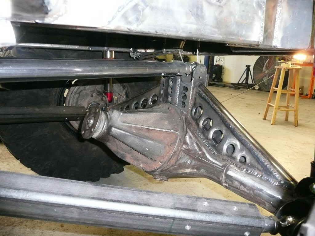
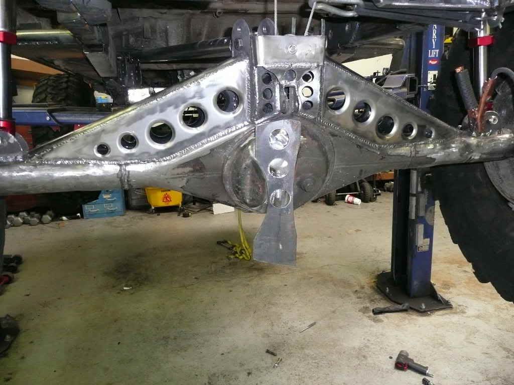
I got the front side of the truss all welded up, then painted the inside and welded up the back.
P1010833.jpg

Back side and the start of some diff protection
P1010835.jpg

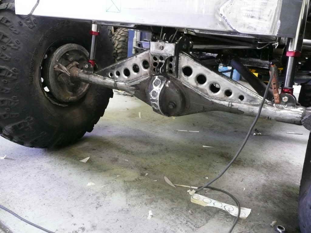
With a little love from my little ball-ping and some welding
P1010838.jpg

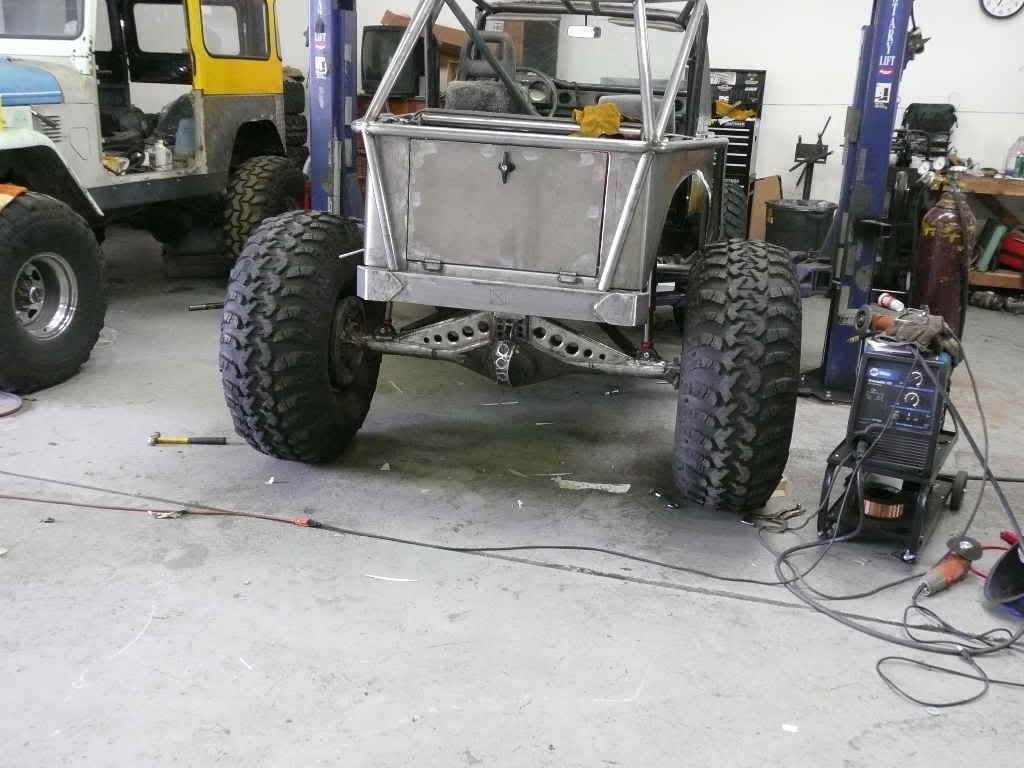
another shot at ride hight
P1010841.jpg
 

suisuki

Chrome Won't Get ya' home
Location
Murray, UT
That looks killer!! :cool:


:eek:
You know you have done a good job when Cody wants to see a SAMI on the trail!!
:cody::rofl:

Thanks, That's funny
I think 'cause he's seen this one in person and knows it's not the average Sami his perception has been altered a bit......;)
 

suisuki

Chrome Won't Get ya' home
Location
Murray, UT
Ok, I new I needed some drivelines but didn't want to fork over the $$$ so here's what I did.
First, I grabbed some cores out from under my '84 parts Toy pickup, and found that the stock rear driveline was nearly perfect for the front of my application except that it was ~1" to long Doh! So I cut the yoke end off to shorten it and found that the factory tube is like paper thin (0.067" I think), I knew that it wouldn't last over one rock so, off to Driveshafts Utah for some high-carbon-steel dom seamless tubing. This stuff is .120 wall so it should hold up a little better. (a little not a lot)
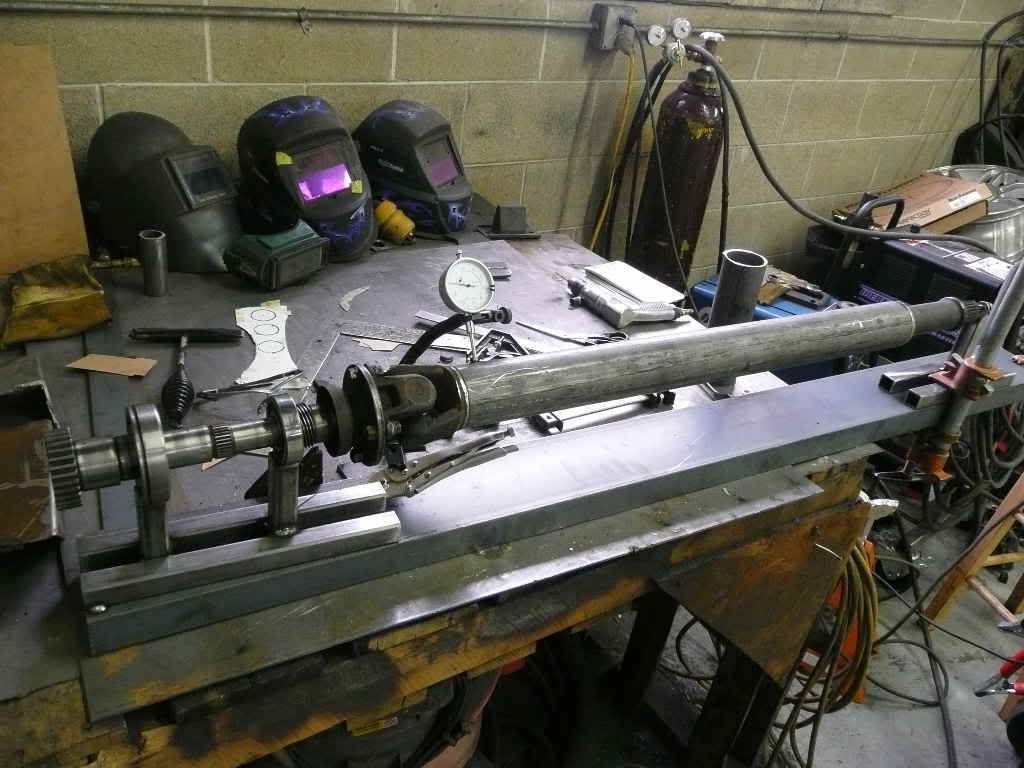
So I cut the slip spline off the old tube and set about making a driveline jig. Like the ones I've seen others like 4rnrRick use.

It's just the spare output shaft and some bearings left over from my dual t-case set-up, with the spare output flange bolted to the end.
P1010846.jpg

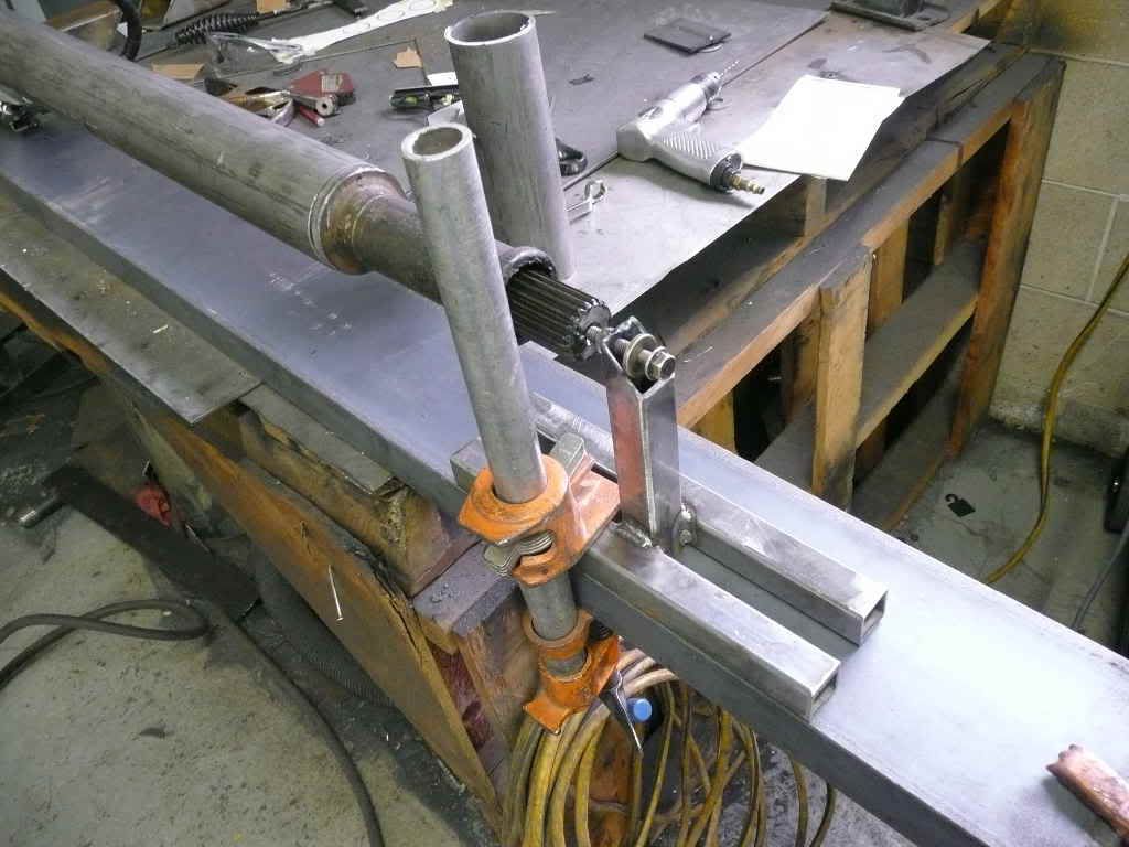
The other end is just a nut welded in some 1" square tube and a bolt. The whole thing is sitting on a piece of channel but, a flat bench (not like mine) or other flat surface works. You just need to have something you can clamp it to.
P1010847.jpg


This set up allows you to rotate the driveshaft with a dial-indicator attached to the base and acurately measure runout. And you can ground your welder thru the bolt end and not worry about welding thru your u-joints. I was suprized at how far off my "eyeball" strait shaft was once the first measurements were taken.
With a little tap-tap from the hammer and a little time you'll have a nice straight/true driveshaft.
A couple tips I learned in the process, before you cut the ends off your tube make a strait mark all the way from one end to the other, that way you can keep your yoke lined up with your slip splines and keep your shaft ends "in-phase". Then, cut the ends off. Next, make a strait line down the new tube and line that up with the marks you made earlier on the yoke and slip splines.

Mount the shaft into the spinning jig. Get one end strait go to the other then back to the first and then back and so on till you have very little to no run-out then start tacking. Make sure you do your tacks in a cross pattern as the heat will move things around a bit. Start with just the smallest tacks on opposite sides, once you have all four opposing sides tacked on both ends you can go back and start to build your welds up, continuing the crossing pattern. Before you know it you'll have a nice strait shaft and will have saved yourself some $$$.
 
Last edited:

suisuki

Chrome Won't Get ya' home
Location
Murray, UT
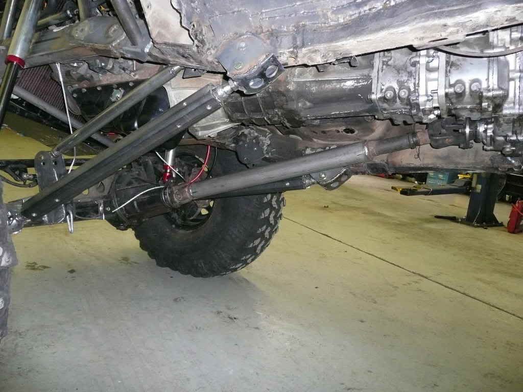
Here's the finished rear driveline it's from the front of the '84 Toy and has a D.C.C.V. joint at the output end. This allowed me to rotate my rear pinion up quite a bit thus increasing driveline ground clearance and allowing for the possability of clearancing my rear diff in the future, which would give me around another inch of clearance, not much but that has the same effect of going from 33's to 35's so.......some day.....maybe.
P1010852.jpg


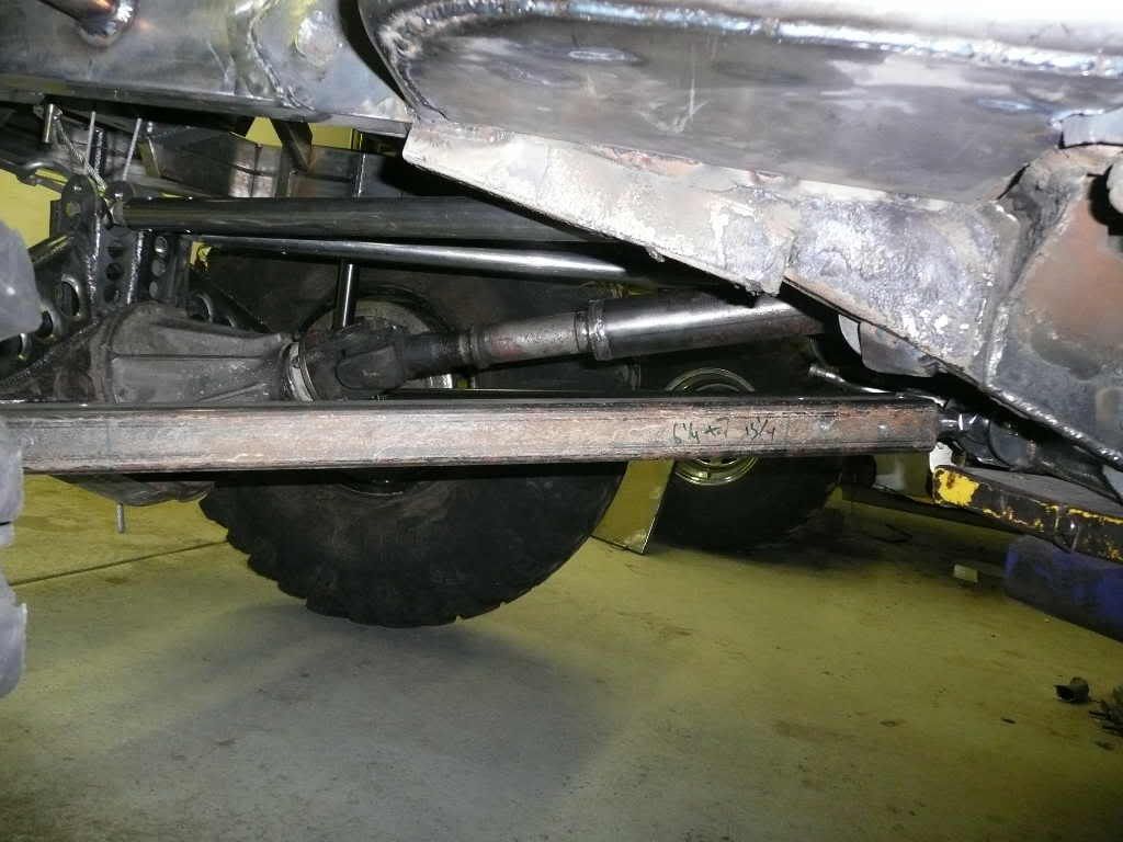
And here's the front. It's pretty well out of harms way as the lower link will serve as a bit of a gaurd, but I'm sure I'll still manage to find some rocks with it.
P1010880.jpg
 

suisuki

Chrome Won't Get ya' home
Location
Murray, UT
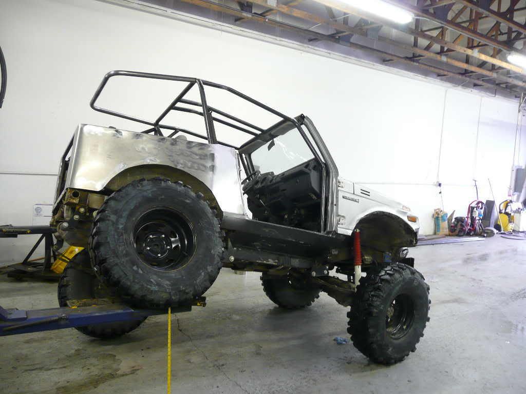
Well I charged the shocks today 205 psi up front and 135 psi in the rear, that gives me 5"s of uptravel in front and 6"s in the rear with a flat belly hight of 24"s. The shocks feel a little soft and I'm sure I'll have to play with the oil levels a bit to get them just right.
P1010882.jpg


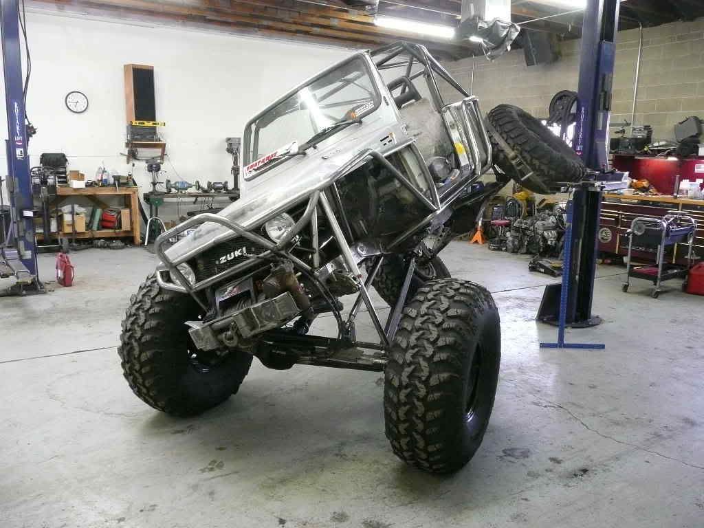
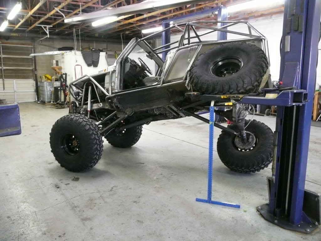
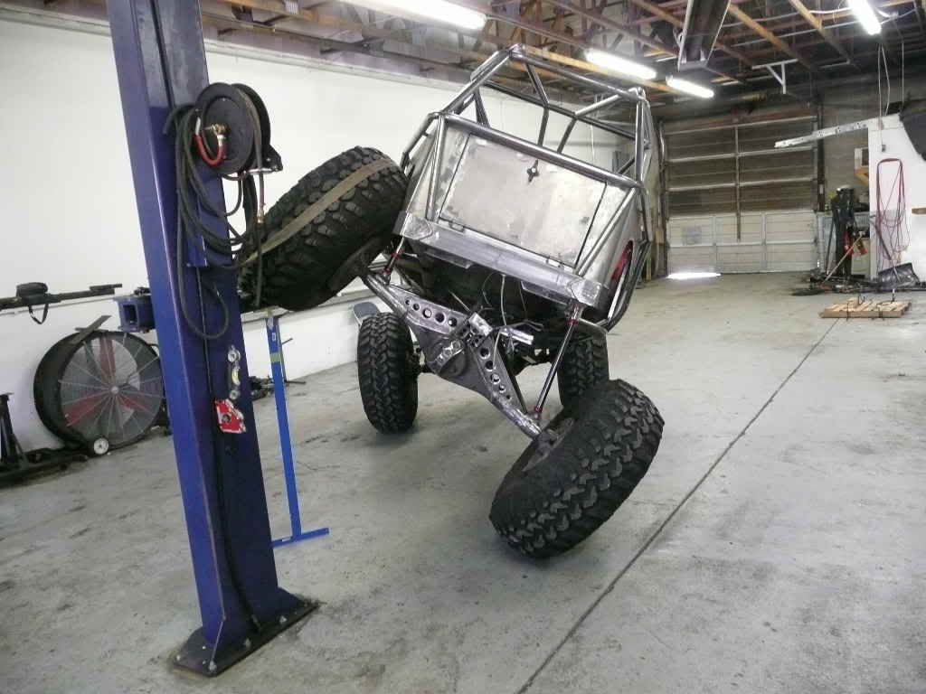
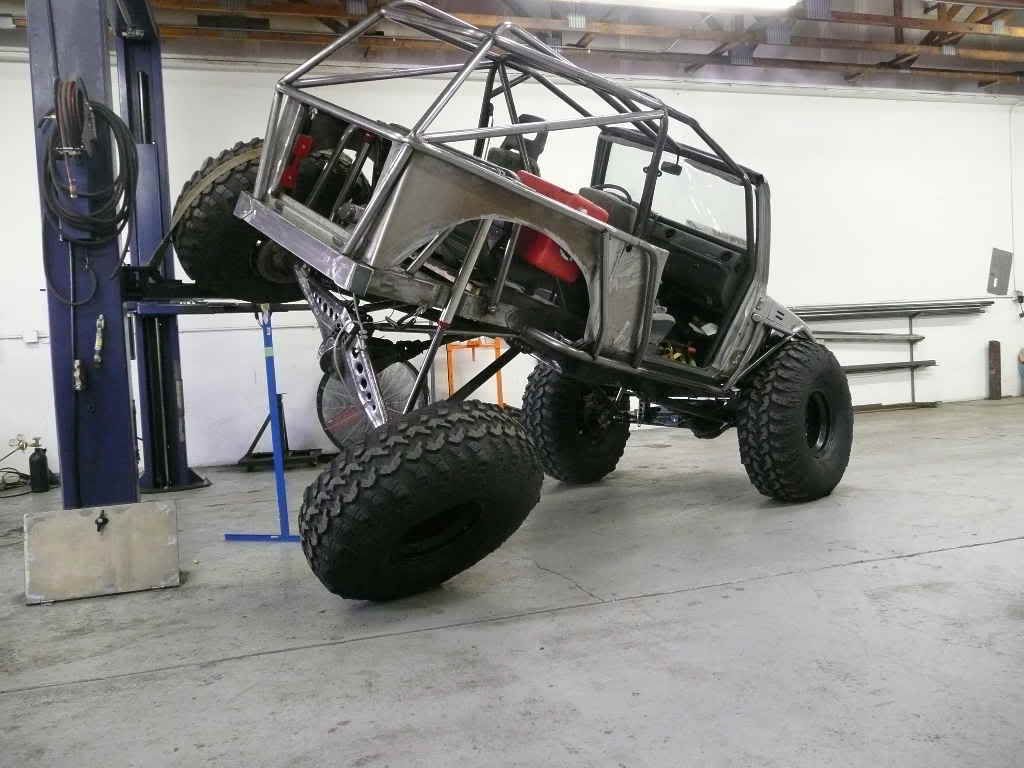
Anyway here's a couple flex shots, see if you can spot the 4 foot T-square.
P1010876.jpg


I had to tape the 48" square to the hoist arm as there was nothing to lean it against, I measured 56"s to the tire, and still had 2.5"s of up travel left in the left-rear shock. I didn't dare go any higher!
P1010872.jpg


Couple more
P1010879.jpg


.
P1010878.jpg
 

suisuki

Chrome Won't Get ya' home
Location
Murray, UT
Thought I would take some preliminary articulation measurements for comparision later

here I'm getting about 29.5" under the rear tire, not bad for a 79" wheel base
P1010027.jpg

It was ok with the Yj springs @ 29.5"s but......

I think I like it better now :rofl:
 
Top