Topic of Discussion Linked Suspension Discussion & Tech Articles

Greg

I run a tight ship... wreck
Admin
There have been some very well written articles about setting up a linked suspension that have been lost over time, I thought it would be a great idea to have those saved for posterity and posted on RME so we can continue to reference them. RME has been around 20 yrs at this point, so I feel like they're in safe keeping here. I did not write these, I will be copy & pasting the information here with credit going to the guys that wrote the information. They made all the effort and deserve the recognition.

One of the best (IMO) written articles that was pretty generic and simplified is an article written in Petersons 4Wheel & Offroad, which is now out of print. I don't remember when it was published... 2002 or so? Fortunately it still exists online here. Written by Fred Williams and published to Petersons 4Wheel & Offroad.

Four-Link Tech - Part 1 ; What Is a Four-link? And Is It For You?​

By Fred Williams​


Photography: Fred Williams, Jerrod Jones​


Part I

A four-link suspension uses links to locate the axle from moving side to side and front to back, while allowing it to travel up and down and articulate. We must agree with the current majority that a four-link suspension with coils, coilovers, quarter-elliptics, or air springs is definitely cool, and that is the most common argument for building your own setup. The problem arises when you think you know what you are doing and just start putting bars and links under your truck. Just because you saw it on some race truck or rockcrawler doesn’t mean you need it for your weekend wheeler, though we have no problem with building one just because you want to try it.


There are some definite benefits to running a four-link, but to do it right takes time, money, and some more time and money. We hope to give you a realistic overview of a simple rear four-link suspension, but first, the pros and cons of building one. The choice is yours, but please consider everything before you get started. The fact remains that a well designed and tested four-link will provide a superior translation of power to the ground and higher ride quality than a leaf-sprung suspension. The secret is really in the testing portion. If you build a four-link on your rig then be prepared to fine-tune it and tear it apart quite a few times before it works right. And during this testing stage we would not recommend driving it to work on the highway at 60 mph. You may get lucky the first time, but if not, remember that tearing your truck apart and re-building it is fun.

Considerations
The biggest question with building a four-link is how long should the links be and where should they attach to the frame and axle. This alone will determine how the axle pushes the vehicle, if the rear of the vehicle lifts or squats under acceleration, if wheel articulation causes the rear axle to pivot and steer, and how the body rolls in turns and over obstacles. The desired amount the vehicle does each of these things is different depending on what the vehicle is designed to do (go fast, corner, crawl, articulate) and how the driver desires the vehicle to respond on different terrain. There is no one right way to build a four-link the same as there is no one perfect off-road vehicle, but it can be tuned to do certain things better than others.

For most truck owners an all-around four-link is the desire, but that will not necessarily be the best rockcrawler, desert jumper, and mud bogger suspension. In addition to all the geometry of designing a four-link there is also the problem of what will actually fit on the vehicle you are building. Will the frame support the links where you want them? Will the fuel tank, exhaust, crossmembers, and driveshafts all fit with the links and allow for proper articulation? Unless you are building a truck or buggy around the suspension, plan on doing some compromising to get the best setup you can. If you are starting to like the idea of keeping the leaf-spring suspension, we don’t blame you. If you are up for the challenge, stay tuned for next month where we start getting into the technical part of the buildup.

Till then you have a bit of homework. You’ll need to round up a tape measure, a calculator, graph paper, and a pencil. Now go measure your wheelbase and decide on the height of the tires you want to run on your rig. Follow that by measuring the rear axle width just inboard of the brake-mounting plates and the height of the frame at various points between the axles along the framerails while the truck is on level ground. Next find the height of the top center bolt of your bellhousing to the ground. Plus start doing research of where you can buy the materials we mentioned below. Just remember you will want to wait until you have read the second part of this story next month before you attack the four-link issue under your truck.


4linkPic1.jpg


The benefits of a four-link over a simple leaf-spring suspension include controlling axlewrap, better departure angles, controlling axle path, and reducing the uncontrolled variables of axle movement down to just spring rate and shock valving. In addition, a four-link can also allow for more travel and articulation that can provide more traction, though we feel that too much of both can cause problems. Weight is also a concern of the modern-day wheeler since excessive weight eats power. Though a coil spring is lighter than a leaf spring, when you consider the weight of the links and mounts and everything else, the gains in weight are minimal.


The major benefit of a leaf-spring suspension over a four-link is cost and maintenance. It will take more time and money to remove leaf springs and design, build, test, and rebuild your four-link than it would to just put on a good leaf suspension, and this is if you do it yourself. With shop rates ranging from $25 to $75 per hour, a professionally fabricated four-link is gonna take a serious bite out of your wallet. Plus we have seen some very impressive leaf-sprung suspensions that allow plenty of travel and articulation.


Material is an important factor and concern for strength and safety. Your lower links could be hitting trail obstacles depending on how low you mount them to the axle, so we would recommend no less than 1 3/4-inch DOM tubing with 0.25-inch wall thickness. If your truck is a fullsize or extremely heavy, or if you are planning on mounting your shocks on the lower arms like some race trucks, then you will want to go to an even larger tubing size, or better yet, sleeve the 1 3/4 x 0.25 with a slightly larger piece of tube. The upper links are less likely to be hit by rocks and such, but we still do not recommend anything less than 0.120 wall, 1 3/4-inch DOM tubing.


4linkPic2.jpg


As for the joints at the ends of the links, get the best you can afford. The links will last longer and be stronger if you spend the extra dimes, plus if they fail it can be tragic. Everything from Johnny Joints to Heims are applicable. Many Companies like Poly Performance and Avalanche Engineering can supply you with these joints and the proper weld-in bungs to screw them into the links. And remember that the mounting bolts should be as close to perpendicular to the link as possible when installed at ride height to get the maximum strength from the joints.


4linkPic2.1.jpg


For the mounts we will steer you toward 0.25-inch-or-larger material. Many shops like A&A Manufacturing, McKenzies Performance Products, and circle-track race shops offer tabs and brackets that can be welded to frames for link mounts if you don’t have the facilities or tools to cut and build your own. As for the axle mounts, your upper-link mount will most likely be a bracket that bridges over your differential housing. Welding directly to the cast housing is tricky and if you don’t know how then plan on building a bridge out of 0.188 wall 1 3/4-inch or larger DOM or square tubing.


4linkPic2.2.jpg


Grade 8 hardware is the best bet for attaching all the links to the brackets, and should be at least 7/16 inch if not larger. Remember when you have everything together that, like everything else on your off-road machine, you should check for loose or broken parts before trail runs.


Greg

I run a tight ship... wreck
Admin
PART II


4linkPic3.jpg


Last month we started an in-depth look at the benefits and detriments of a four-link suspension. We touched on how a four-link will reduce the number of variables down to just the spring rate and shock valving. In addition, a four-link is expensive to do right, and this second installment will hopefully take you from the drawing board to the garage floor.

There are many different link configuration possibilities, but for this discussion we’ll stick to a basic four-link where the upper two links start at the frame and converge at the top center of the rear axle. The lower two links will also run from the frame to the outer ends of the axletubes. A three-link is similar, but the upper links are replaced by an A-arm with a single joint at the top of the axle. The three-link setup puts that upper axle joint under greater side loads than the upper two links of a four-link, but it is a viable alternative. Also, suspension builders will argue till the cows come home about what works best, but what we have done is discuss with some of the top desert-race suspension builders how to get you started on a four-link. This design is just a launching pad, and you will need to spend a fair bit of time dialing everything in.

In addition there are many excellent books available to learn more about suspension design. We would recommend:

Chassis Engineering
by Herb Adams
Fundamentals of Vehicle Dynamics by Thomas D. Gillespie
Race Car Vehicle Dynamics by Milliken and Milliken.

Though some of these books are pretty heavy, they do help explain the theories behind four-link suspensions, but mostly when applied to street cars and not off-road vehicles. To truly explain a four-link, we would need this entire magazine and a few engineering degrees, and even then there would be things that would be missed. This, however, should be enough to get you started. Just take your time and enjoy the process, because if you don’t have the patience to adjust and rebuild your suspension until it works just right, then you should stick to leaf springs.


The first step in building a four-link involves a tape measure and some graph paper. What you are going to do is figure out the angle of the links and their mounting locations. This will in turn give you an idea of where to start building your four-link. From there you can fine-tune it. Park the truck on flat ground and measure your wheelbase and the tire size you will be running. Plot the axle centerline points on the bottom half of the graph paper as if you were looking at the side of the truck. Now draw the framerail as it sits above the axle centerlines. This should be where you expect the frame to sit above the axle if you have not yet lifted it. If you know the height and location of your center of gravity of the sprung weight, plot that as well. If not, estimate it by measuring from the top center bolt of the bellhousing to the ground. You may need to add the height of the expected lift if the truck is still stock.

Now plot a point on the front center of the rear axletube. This will be your lower link mount. Some people mount this above or below the axletube, but we have found that the important part is more the difference in height from the upper-link mount. If your truck is going to be very tall, you may want to put these links on the top of the axletube. To find the upper-link axle-mount point, multiply the tire diameter by 0.25 (25 percent). Use that number as the distance in inches that the upper link will be above the lower link at the axle. If you were running 36-inch tires, you would want the upper links to be mounted 9 inches above the lower-link mount. You will most likely be mounting the links 8 to 11 inches apart. The farther apart you can get them right now, the better, as this will help control the leverage of the tires and fight axlewrap. The limiting factor will most likely be the bed of the truck. Continue by plotting the upper- and lower-link axle-mount points. If this is getting confusing, then you are normal; if it’s clear as a bell, you may be a bit too smart for your own good.


Since you have a rough idea of where your axle-mounting points will be, it’s time to move onto the frame mounts. The first point to plot is the lower-link frame mount. To determine this, draw a link with a 5 to 10 degree angle up from the axle mount to the frame in the sideview drawing. Watch where the link intersects with the frame; this point will most likely be near the transfer-case rear output. It should also be as high as possible for ground clearance, but low on the frame to keep the link as level as possible. If you cannot get the link to intersect the frame at 5 to 10 degrees, you may need to move the lower-link axle mount up on the axletube. If so, you will also need to move the upper-link axle mount as well to keep the predetermined 8- to 11-inch vertical spacing between the links at the axle.

4linkPic4-1.jpg


Figure 1
4linkPic4-2.jpg


Figure 2
4linkPic4-3.jpg


Figure 3
Another option is to consider building a crossmember mount below the framerails. At this point you should be realizing that a four-link involves tons of variables and compromises, and we haven’t even gotten to actually looking under the truck yet! Now take the horizontal distance from the lower-link frame mount to the lower-link axle mount and multiply that number by 0.7 (70 percent). This is a good horizontal length of the upper links. The distance apart that you mount the upper and lower links on the frame should be about half the vertical distance apart of the link’s axle mounts. Again, try to keep the links as level as possible.

Start looking at the width of the frame at the point where the upper links attach, and write this measurement down. Subsequently measure the distance along the axletube from just shy of one brake mounting plate to the other. This will be the distance apart of your lower-link axle-mounting points. If at this point you are starting to really like the idea of leaf springs, then we congratulate you for having some common sense. If you are still thinking that you’ll be the talk of the town with your new super four-link suspension, then dig out that piece of graph paper and sharpen your pencil, because there is more work to do.


If you have a pile of graph paper crumpled into balls and a headache from thinking too hard, then you are right on track. The tricky part comes when you take your drawing and see if you can actually attach the links you drew on the truck’s frame and axles. This is where compromise comes in. You may need to move the fuel tank, exhaust, or various other low-hanging parts of your truck. There is always a bit of adjustment available. The upper links can be slightly longer or shorter than 0.7 (70 percent) of the lower links, but try not to pass 0.6 (60 percent) or 0.8 (80 percent).


On the graph paper draw lines up to the top of the paper from the front- and rear-axle centerline, upper- and lower-link axle, and frame-mounting points. Next, in the upper space draw the rear axle from the top view with the lower-link axle mounts plotted at the distance apart you measured from the actual rear axle. Follow that by drawing in the framerails from the top view with the center of the frame over the center of the rear axle. But wait, there’s more.

Draw in the upper links first. Remember to have them start from the frame, but at the axle keep them slightly separate to allow access to the nuts that will go on the ends of the bolts running through your rod ends. Now grab an angle finder. It is very important that the angle of the two upper links be no less than 40 degrees. This angle is what locates the axle laterally or side to side. The smaller or more shallow the angle, the weaker the lateral control. This again may mean shortening the upper links, but try not to make them less than 70 percent of the horizontal length of the lower links. If need be, you may need to shorten the lower link’s horizontal length as well, but try to keep them as long and as level as possible. If you are wondering when you get to start installing your really cool new coilover shocks, then you might need a lesson in patience. Get another cup of java and keep studying.

To reduce the rear steer of the axle, we need the tire to move towards the center of the frame, side to side, as it articulates and not towards the center of the frame, front to back. First you need to draw in lines extending from the links until they converge when viewed from the top of the vehicle. These convergence points are known as the lateral constraint points (LCP). The upper-link’s extended lines will most likely converge at a LCP just behind the rear axle. The lower-link’s extended lines should converge at a LCP somewhere forward of the transmission, depending on how much of an angle you give them when looking at the top view. An angled set of lower links helps the upper links locate the axle laterally and fight rear steer, but also requires a larger area to slide over obstacles. The best route seems to be a slight angle, but not at severe as the upper links. An acceptable angle will have the lower link’s separation at the frame equal to 50 to 70 percent of axle-mount separation, which may require fabricating a crossmember to mount them to, as discussed earlier.

Moving on, take your center of gravity height measurement and multiply it by 0.5 (50 percent) and write down your answer. Now multiply the height by 0.8 (80 percent) and write that down. Next, draw a vertical line through the front axle perpendicular to the ground, and plot two points using your answers above as the number of inches from the ground. The space between these two points represents the percent of antisquat you will be aiming for. This will be discussed further in Figure 9.

Next draw a vertical line down from the LCPs to the sideview drawing. Extend lines from the upper links back and lower links forward until they cross the lines you brought down from the LCPs. This will show you the heights of the LCPs. Now when you connect the two LCPs on the lower drawing with a straight line, you will get the roll axis. This is the imaginary line perpendicular to which the axle will articulate. As such, you want the front of the roll axis slightly lower than the rear. This will give better handling and less rear oversteer as the axle articulates. If your roll axis leans toward the back of the truck, you may need to lower the upper link’s frame mount or increase the height of the axle bridge. Just don’t let the upper link’s frame-mounting point get lower than the lower-link’s frame-mounting point—better yet, keep them apart. As you can see, there will be many opportunities to adjust and diverge from the original design to get the geometry correct.


To make sure your suspension transmits power to the ground, you want a certain amount of antisquat. This will let the tires move the vehicle forward without the energy compressing or expanding the suspension. The perfect amount of antisquat is debatable, depending on the driver’s desires. Some want the vehicle to crouch when accelerating, but this is sending the power into the springs. Some want the vehicle to lift under acceleration to gain more traction, but this can let the axle walk under the vehicle instead of propelling it forward. We will try to design the suspension not to squat or lift excessively, while erring on the squat side. The way to determine antisquat is to run a line from the contact patch (CP), or center of where the rear tire touches the ground, to a point where the upper and lower links would converge in the front of the vehicle while viewed from the side.​
4linkPic4-4.jpg


Figure 4
4linkPic4-5.jpg


Figure 5
4linkPic4-6.jpg


Figure 6
4linkPic4-7.jpg


Figure 7
4linkPic4-8.jpg


Figure 8
4linkPic4-9.jpg


Figure 9


The point towards the front of the vehicle where the links would converge is known as the instant center (IC). The line from the instant center to the contact patch of the rear tire should run across the vertical line through the front tire. If it is within the 50 percent to 80 percent of the center of gravity height at the front tire that we determined in Figure 7, then it should be a good amount of antisquat to start from. If you want it to lift more, you need the line to be closer to the center of gravity or above 80 percent. If you want it to squat more, you want the line closer to the ground or below 50 percent. Now if the antisquat is not where you want it, you must start adjusting the link-mounting points. If you move the lower axle point up on the axle, remember to raise the upper link’s axle mount as well. If you move the lower link’s frame mount, then you may need to move the upper link’s frame mount as well. Then after you think you have gotten the links where you want them, move your new dimensions back to those of Figure 8 and make sure your roll axis is angled towards the front of the truck. Expect to spend many long hours moving your measurements back and forth between Figures 8 and 9 until you have everything dialed in.


Once you have all this figured out, it’s time to start on the truck. Begin by building your axle bridge to mount the upper links to the axle and the lower link’s axle mounts as well. Remember to set your pinion angle first, depending on whether you will be running a CV or U-joint, and then only tack-weld everything. If you need to change it, this will make moving parts that much easier.

4linkPic5-1.jpg


Next, build the bracket to attach the lower links to the frame. You may want to build a crossmember for this if you determined that you need it to get a better roll axis. These brackets may also become skid points when you encounter obstacles, so you might want to build their forward edge with an angle to help slide over things.​

4linkPic5-2.jpg

4linkPic5-3.jpg


Just be sure to use the proper materials we discussed last month, as there is a fair bit of force put on all of these points. Plus, if you are not a skilled welder, or this is your first welding project, stop right now. The welds on these components must be very good; if they fail, it can be fatal.

When you get to the upper link’s frame mount, we recommend using a bracket that has multiple holes drilled for attaching the upper links such as this one from A&A Manufacturing. Attach this bracket so you can move the upper link’s frame mounts up and down from the ground. This will be your initial point of adjustment to fine-tune the suspension whether you are going racing or rockcrawling.​

4linkPic5-5.jpg


Now that you have everything in place, it is time to cycle the suspension. Notice if the axle moves straight up and down as it should or if it swings forward as it articulates, as it shouldn’t. Are the links and rod ends binding? If so, do the brackets need to be angled to follow the line of the links? Plus, what about everything under the truck—exhaust, fuel tank, spare tire, and so on? Is there clearance for these or do they need to be moved? If everything seems to be right, it’s time to burn in the welds. Just remember that it is not uncommon to need to tear into the suspension again to get it to work a bit better. Do not be surprised if you are adjusting things three or four times before you get it how you like it. You may still want to change more, depending on the terrain you encounter or the driving style you prefer. This is only one way to build a four-link, and different builders will try different methods. If you enjoy a challenge and are willing to spend the time, money, and energy to fine-tune your suspension, then a four-link may be right for you. If not, then stick to a professional kit, or leaf springs, and just go have fun on the trail.​


Last edited:

Greg

I run a tight ship... wreck
Admin
Here is another article from crawlpedia.com that covers the same subjects, with a slightly different approach to the tech. Again, some very good information here. Copyright by Crawlpedia- https://www.crawlpedia.com/4_link_suspension.htm

4-Link Suspension Guide:
Anti-Squat, Anti-Dive, & Roll Center​


One of the most common questions we get about suspension setup and tuning is how 4-link geometry affects the performance and handling of a vehicle. In this article we'll cover what we consider to be the three most important elements: anti-squat, anti-dive, and roll center.

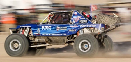
Ultra4 Racing Suspension


The Basics of Anti-Squat, Anti-Dive, and Roll Center


When building a 4-link suspension, the lengths of the links, their positioning, and the angles at which they are mounted, will all determine how the suspension affects the vehicle chassis under acceleration, braking, and cornering. While a chassis with too much body roll can easily be improved with the addition of a properly tuned sway bar, undesirable rear squat and front nose dive characteristics can only be fixed be changing the 4-link geometry. To emphasize that point further, and because it is a very common mistake, a vehicle with too much rear squat under acceleration or too much nose dive under braking cannot and should not be fixed by using heavier springs and/or shock valving. These unwanted characteristics are caused by incorrect 4-link geometry and they can only be improved by changing that geometry.


Don't Over-Think It: There are many thick textbooks, expensive software, and hundred-page internet forums out there on the subject of 4-link geometry and it is very easy to get lost and frustrated. You are not building a Formula 1 racecar so don't expect to be plotting the movement of your suspension under every posible situation. The best advice we can give is to not over-think it, as long as you are familiar with the basic concepts of anti-squat, anti-dive, and roll center, and the axles move nice and smooth when you cylce the suspension, you will be in great shape.


Download a 4-LInk Calculator


The first step in either building a 4-link suspension or troubleshooting an existing suspension is to download one of these Triaged calculators created by Dan Barcroft and plug in the dimensions and weights it asks for. While they may look complicated, they are actually very easy to learn by just entering numbers and watching the outputs and graphics change.

Triaged 4 Link Suspension Calculator (.xls)
Triaged 3 Link Suspension Calculator (.xls)


Rear: Anti-Squat Explained


Anti-squat in a linked suspension system determines how the rear end of a vehicle moves under acceleration or upon the rear axle contacting an obstacle at speed. The anti-squat value is determined by the vertical angle of the rear links as they relate to the front axle position and the center of gravity of the vehicle.


How to Calculate Anti-Squat:


  1. Find the horizontal center of gravity height of the vehicle or use the crankshaft. (Yellow)
  2. Draw a line from the center of the front tire contact point up to the center of gravity line. (Dotted Green)
  3. Draw a line from that intersection to the center of the rear tires contact point. (Solid Green)
  4. Draw lines to extend the upper and lower rear links and find the point where they intersect. (Instant Center)
  5. The vertical distance from the ground to the instant center is the anti-squat value.

How Anti-Squat Affects the Vehicle:


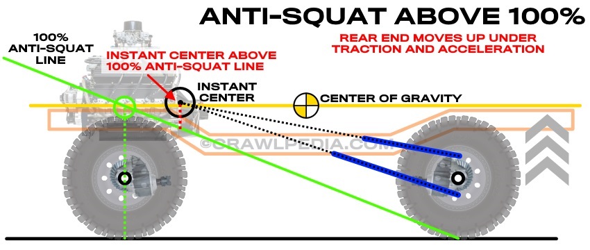
  • Anti-squat above 100% causes the rear end to move up and the suspension to unload under acceleration.
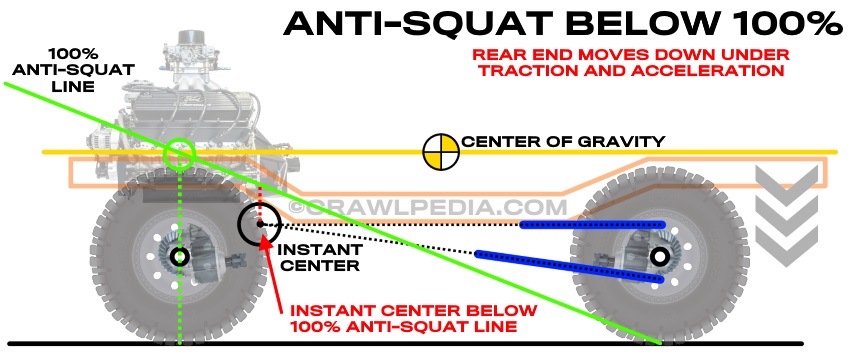
  • Anti-squat under 100% causes the rear end to move down and the suspension to compress under acceleration.
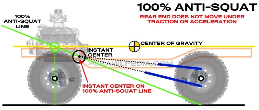
  • 100% anti-squat results in no movement under acceleration.


Rear: Anti-Squat Over 100%


Suspension Anti-Squat Above 100

Suspension systems with anti-squat values over 100% will cause the rear end of the vehicle to raise up and unload the rear suspension under acceleration or when the rear tires contact an obstacle at speed. These characteristics are desired for drag racing and heavy acceleration applications because the forces that push the rear end up also push the rear tires down for more traction. At speed, however, when the rear tires impact an object, that immediate increase in traction will cause the power applied to the rear axle to raise the chassis up at the same time as the suspension is trying to compress and absorb the impact.


  • Anti-squat between 140% and 180% works well for drag racing on smooth pavement with heavy rebound valving.
  • Anti-squat between 110% and 150% works well for hardcore technical rock crawling and some styles of rock bouncing.
  • Anti-squat between 100% and 130% works well for mud drag racing and some hill-n-hole racing.


Rear: Anti-Squat Under 100%


Suspension Anti-Squat Below 100

Suspension systems with anti-squat values under 100% will cause the rear end of the vehicle to drop down (squat) and compress the rear suspension under acceleration or when the rear tires contact an obstacle at speed. These characteristics are desired for desert racing to absorb rough terrain at speed because the impact forces are transferred directly to the rear suspension. Under hard acceleration, however, some of the power applied to the rear axle is used to compress the rear suspension which lifts up on the tires and robs traction and power.

  • Anti-squat between 10% and 50% works well for high speed desert racing.
  • Anti-squat between 20% and 80% works well for open road racing and rally racing.
  • Anti-squat between 70% and 100% works well for rock crawling and trail running.


Rear: 100% Anti-Squat


Suspension Anti-Squat at 100


Suspension systems with 100% anti-squat values will have no effect on the chassis under acceleration or when the rear tires contact an obstacle at speed. These characteristics make the vehicle neutral and keep the power and suspension dynamics independent. While it's rare to have a vehicle permanently set up at 100% anti-squat, many people choose to make their suspension systems adjustable to above and below 100% anti-squat.


  • 100% Anti-squat is a good universal default starting point for a multi-purpose vehicle.
  • Anti-squat between 80% and 120% works well for almost every off-road application (excluding desert racing).
  • Anti-squat between 80% and 120% works well for almost every street and track application (excluding drag racing).


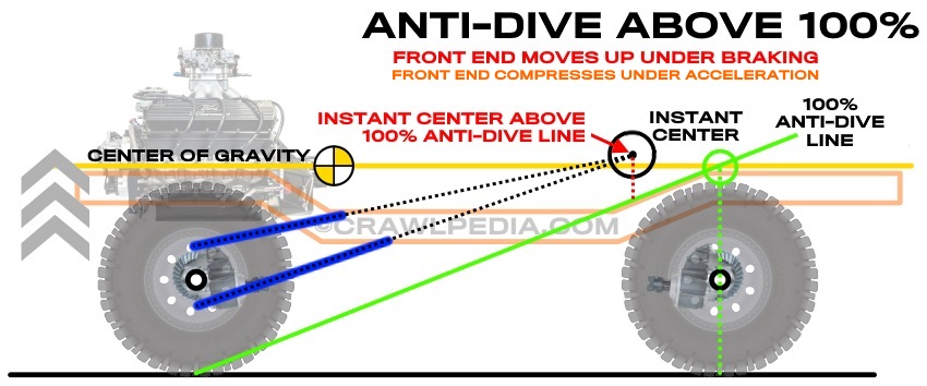
Front: Anti-Dive Explained

Anti-dive geometry in a linked suspension system determines how the front end of a vehicle moves under braking and acceleration. The anti-dive value is determined by the vertical angle of the front links as they relate to the rear axle position and the center of gravity of the vehicle.


How to Calculate Anti-Dive:


  1. Find the horizontal center of gravity height of the vehicle or use the crankshaft. (Yellow)
  2. Draw a line from the center of the rear tire contact point up to the center of gravity line. (Dotted Green)
  3. Draw a line from that intersection to the center of the front tire's contact point. (Solid Green)
  4. Draw lines to extend the upper and lower front links and find the point where they intersect. (Instant Center)
  5. The vertical distance from the ground to the instant center is the anti-dive value.

How Anti-Dive Affects the Vehicle:

  • Anti-dive above 100% will prevent the front end from compressing under hard braking and stiffens the chassis.
  • Anti-dive above 100% will compressing the front suspension under hard acceleration in a 4x4 application.
  • Anti-dive above 100% will significantly reduce rear weight transfer under hard acceleration.
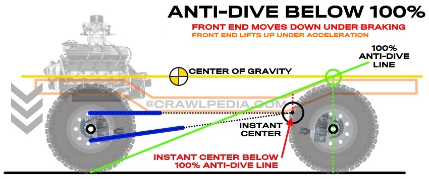
  • Anti-dive under 100% causes the suspension to compress under braking.
  • Anti-dive under 100% causes the suspension to extend and lift under 4x4 acceleration.
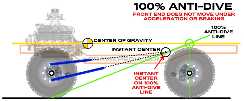
  • 100% anti-dive results in no movement and transfers all energy into the chassis.


Front: Anti-Dive Over 100%


Suspension Anti-Dive Above 100

Suspension systems with anti-dive values over 100% will cause the front end to stiffen up under hard braking to prevent the suspension from compressing which is ideal for aggressive braking and hard cornering. Under hard acceleration, high anti-dive geometry will cause the suspension to compress, thus keeping the front end down and under tension which is desired for steep hill climbs. As a trade-off, a suspension system with a high anti-dive setup with be less able to absorb rough terrain under hard braking as is required by rally cars and short course trucks.


  • High anti-dive suspension geometry work well for aggressive street driving or pavement racing.
  • High anti-dive suspension geometry is desired for hill-climb racing as it keeps the front end down under acceleration


Front: Anti-Dive Under 100%


Suspension Anti-Dive Below 100

Suspension systems with anti-dive values under 100% will cause the front suspension to compress under breaking, often called nose-dive. Under acceleration, a low anti-dive geometry will cause the front end to lift and the suspension to extend which also shifts weight to the rear of the vehicle. These characteristics are great for aggressive driving on hard packed dirt tracks and hill climb racing. Many mud-drag racing vehicles use low anti-dive geometry to shift weight to the rear axle under acceleration and extend the front suspension to better absorb the terrain. Unfortunately, vehicle's with low anti-dive suspension geometry may experience excessive nose-dive under hard braking.


  • Low anti-dive suspension geometry works well for rally racing or short course off-road racing.
  • Low anti-dive suspension geometry is used by many rock bouncers to keep the suspension extended during a climb.
  • Low anti-dive suspension geometry is desired in mud-drag racing to improve rear traction and absorbs rough terrain.


Front: 100% Anti-Dive


Suspension Anti-Dive at 100

Suspension systems with 100% anti-dive values will have no effect on the chassis under braking or acceleration. These characteristics make the vehicle neutral and keep the power and suspension dynamics independent. For many applications, a 100% anti-dive front end may be a desirable starting point or default setting, especially if the 4-link mounts are fabricated to allow for adjustability above and below 100%.


  • 100% Anti-dive is a great universal default starting point for many applications.
  • Circle track racers often use low anti-dive on the left front and high anti-dive on the right front tire for improved left turns.


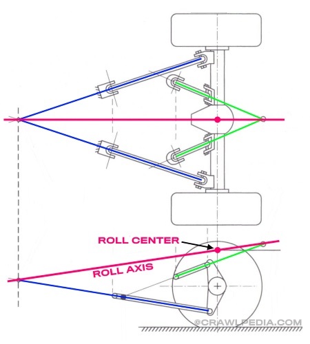
Roll Axis and Roll Center Explained


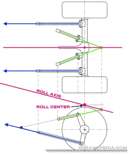
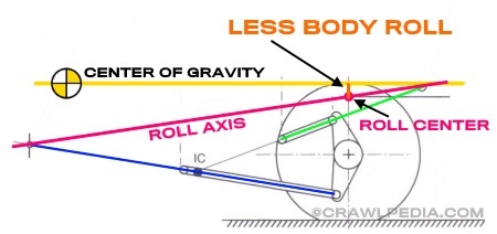
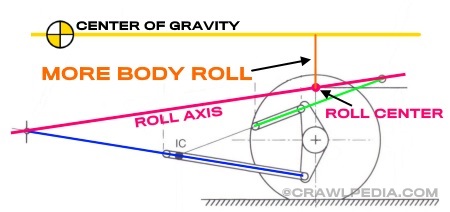
The roll axis and roll center of a vehicle's suspension system determine how much body roll or sway the vehicle will experience when cornering. The roll axis is the imaginary line drawn between the two points made where the lower links would eventually connect and where the upper links would eventually connect. In the case of a suspension with parallel links the roll axis line is simply going to be parallel with the parallel links. The point along the roll axis that is directly above the axle center line is the roll center.


Suspension Roll Axis


Body Roll Explained


The distance between the roll center and vehicle's center of gravity becomes the leverage factor for body roll. In other words, the further above the roll center the vehicle's center of gravity is, the more body roll the vehicle will experience during a turn. The closer the roll center is to the center of gravity, the less body roll the vehicle will experience and, in theory, if the roll center is on the center of gravity line, the vehicle would have no body roll.
Suspension Roll Axis


One additional note about the roll center is that while the center of gravity of the vehicle always remains the same in relation to the chassis, the roll center and roll axis will move as the suspension cycles. For most applications this change in roll axis is not worth considering and the calculations should be done at ride height. For racing applications, however, watching the roll axis as the suspension compresses entering a hard turn may be worthwhile.

Finally, unlike anti-squat and anti-dive that can only be tuned by adjusting the 4-link geometry, a vehicle with too much body roll can easily be improved by installing a properly tuned sway bar without negatively impacting ride quality or suspension performance.
 
Last edited:

Gravy

Ant Anstead of Dirtbikes
Supporting Member
The 4 link calculator by triaged on pirate is good too. ( I see the link above now but it's worth mentioning he put it together in about 2004 and I credit him with lots of the tech I know)


The coilover spring tech thread might be good to bring over too. By Zukizzy
 

1tonblazer

Big Ugly Blazer Pilot
Location
Kamas, Utah
I decided to not make my brain explode when converting my 87 Blazer to a triangulated 4 link/coilover front end, and had Sexton Offroad build my system a few years ago... Mine handles pavement use (85-90MPH over Parley's multiple times) very well actually, well enough I let my teenagers, and niece drive it a lot. It also wheels very well, well enough I let my teenagers and niece wheel it a lot.....
 
Top