You are using an out of date browser. It may not display this or other websites correctly.
You should upgrade or use an alternative browser.
You should upgrade or use an alternative browser.
Midget build?
- Thread starter 1969honda
- Start date
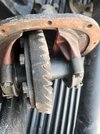
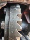
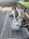
Picked up a complete 8" ranchero axle minus brakes today. Guy had an extra 3rd that he threw in with a newly installed spool and bearings. Said he installed it and quickly realized within a day that he didn't want a spool on the street. After that he swapped a complete 9" into the car for what a new posi would have cost.
I won't be needing the spool for anything, but now I have 2.79, 3.25 and 3.50 gears to choose from. Most likely sell off the spool and use the funds to save for a Eaton truetrac or similar gear drive limited slip.
I won't be needing the spool for anything, but now I have 2.79, 3.25 and 3.50 gears to choose from. Most likely sell off the spool and use the funds to save for a Eaton truetrac or similar gear drive limited slip.
Attachments
I'll try to get pictures up later tonight of this weekend progress. I mocked up the full clutch package and determined I need to shorten the input shaft by about a 1/2 inch. The splines are bottoming out on the bore of the flywheel and preventing the transmission from seating fully.

To make things easier to measure and fully see what the issue was I removed the transmission bellhousing and input shaft. Afterwards I pulled the top cover and tailhousing to inspect the tray of the transmission health. I was presently surprised to get really clean fluid when I drained it, and see what appears to be mint condition shifter fork pads, synchro, and gearing. Like no visible wear of the black nitride coatings or rounding of teeth on the brass synchros.
I then mocked up the input with bellhousing and clutch kit to the block and took measurements of everything. It was much easier to move things and, peek in the bellhousing thru the inspection cover and verify the input bearing was fully seated in the race.

*Notes for me:
Crankshaft counter bore is .823" ID for 1.100", then steps down to about .590 " ID for another .899" of depth.
Input shaft noise is 0.590-.591" in diameter by 0.885" length.
Turning off 0.500" and reducing the shaft to the input nose diameter will allow ~.130 of clearance between the flywheel register and the input shaft.


To make things easier to measure and fully see what the issue was I removed the transmission bellhousing and input shaft. Afterwards I pulled the top cover and tailhousing to inspect the tray of the transmission health. I was presently surprised to get really clean fluid when I drained it, and see what appears to be mint condition shifter fork pads, synchro, and gearing. Like no visible wear of the black nitride coatings or rounding of teeth on the brass synchros.
I then mocked up the input with bellhousing and clutch kit to the block and took measurements of everything. It was much easier to move things and, peek in the bellhousing thru the inspection cover and verify the input bearing was fully seated in the race.

*Notes for me:
Crankshaft counter bore is .823" ID for 1.100", then steps down to about .590 " ID for another .899" of depth.
Input shaft noise is 0.590-.591" in diameter by 0.885" length.
Turning off 0.500" and reducing the shaft to the input nose diameter will allow ~.130 of clearance between the flywheel register and the input shaft.

Last edited:
After getting the input shaft measurements and inspecting the transmission condition I decided to tackle some wiring.
I went thru the wiring connector charts and diagrams for the X190 BCM connector and the auto transmission connector. I used some partners tape and a pen to label every wire and either clipped or depinned each circuit.

In the process I pulled out all of diesel specific circuits, AT specific wiring, rear O2 sensor, A/C circuits and started removing some of the evap system circuits.

Today I've been rereading GMLAN High Speed Serial Data information. Wiring charts have (4) different GMLAN (+) and (-) twisted pairs. I think the #1 circuit is the only one I'll need since I don't have a BCM or any other fancy stuff.
I went thru the wiring connector charts and diagrams for the X190 BCM connector and the auto transmission connector. I used some partners tape and a pen to label every wire and either clipped or depinned each circuit.

In the process I pulled out all of diesel specific circuits, AT specific wiring, rear O2 sensor, A/C circuits and started removing some of the evap system circuits.

Today I've been rereading GMLAN High Speed Serial Data information. Wiring charts have (4) different GMLAN (+) and (-) twisted pairs. I think the #1 circuit is the only one I'll need since I don't have a BCM or any other fancy stuff.
Last edited:
Well I ran into an issue awhile back, the bronze pilot bearing was a tad small on the ID. I ran a 9/16 drill bit with some emery cloth wrapped around it thru the bearing a couple times and everything lines up and bolted together like it was ment to be. Now I need a throw out bearing to verify the mechanical linkage is going to work out.
I had a bearing previously, but when I opened the Timken box up (PN 61463) back in October, it was just a regular tapered bearing race in the box? I looked at the package closer and realized someone had slapped a sticker over the original part number. I bought it thru Amazon so I requested a replacement figuring I wasn't in a hurry with a cervical disc replacement surgery a couple weeks away. The *new* bearing came back a week or so later and I got the same box again with areplaced label and just a race. At that point I took it as a sign that I shouldn't be working on projects until healed up and requested a refund.
I had a bearing previously, but when I opened the Timken box up (PN 61463) back in October, it was just a regular tapered bearing race in the box? I looked at the package closer and realized someone had slapped a sticker over the original part number. I bought it thru Amazon so I requested a replacement figuring I wasn't in a hurry with a cervical disc replacement surgery a couple weeks away. The *new* bearing came back a week or so later and I got the same box again with areplaced label and just a race. At that point I took it as a sign that I shouldn't be working on projects until healed up and requested a refund.
Finally got what I hope it's the right bearing. There's 3 listed for a 98 Isuzu Amigo, so I grabbed the one in stock at O'Reilly and I seems to be correct. I'll have to shave down the push rods on the slave cylinder a little to get spacing correct (sorry forgot to take a picture).
Everything bolted up and I stuck the drive train in the car. It's close in a lot of spaces and engine mounts are going to be fun. This engine is normally transverse with a mount over the belt drive and one off the transmission bell housing.


I have 2" on each side of the transmission at the firewall and significantly less at the bell housing. The crank pulley will clear the steering rack by about 3/4"- 7/8". This coincidentally puts the oil pan drain plug flush with the frame rails.
Everything bolted up and I stuck the drive train in the car. It's close in a lot of spaces and engine mounts are going to be fun. This engine is normally transverse with a mount over the belt drive and one off the transmission bell housing.


I have 2" on each side of the transmission at the firewall and significantly less at the bell housing. The crank pulley will clear the steering rack by about 3/4"- 7/8". This coincidentally puts the oil pan drain plug flush with the frame rails.
Attachments
- Location
- Grand Junction, CO
That 'little' engine looks massive in place! 
jpndave
Member
- Location
- Hyde Park, UT
Holy Crap!! Where is everything? That looks downright roomy in there. Not the engine bay, the garage. I might need you to come work some of that magic over here.
Seriously, looks great! It's got to feel good to get back on and more want to do project.
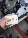
For the engine mounts I think I can land the ears for a typically poly bushing mount over the factory pad. I created some templates for those pads and now I'm trying to wizard together a suitable engine side mount with the bushing.


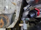
I figure if I can keep the front ear of the frame mount just aft of the factory locating hole, I'll be able to get the bushing bolt in and out on the drivers side. It's pretty tight over there with the water pump, serpentine idler and the steering shaft all trying to occupy the same space. The picture is a little zoomed in, but the engine side plate needs to use the same the bolts as the idler mount.


They are the only bolt bosses on that side of the block big enough and forward enough to work. I may have to try and tie the mount in to the whole side of the block above the pan rail and catch two back towards the bellhousing. The hardest part is they are all in a different plane.

I got a rough idea of my pinion angle using a digital angle finder on the flat face of the pinion flange. The pinion is pointed up towards the trans at 7° currently. Eventually the ford 8" I picked up last summer will be going in and I want to plan for that as I make the engine and transmission mounts.
Next I need to get the chassis fully leveled and blocked to ensure measurements are all accurate. This will be good time to pull the rear axle and slide the 8" under there and get the measurements to shorten it up. I also need to repair a few areas of the chassis that the PO cut out to fit a CA18DET in the car prior to me buying it.
I have a stock '18 Cruze fuel pump and PWM fuel pump controller in the mail and the necessary wiring to go with those. I received a PTFE stainless fuel line kit and fittings yesterday, along with a couple different styles of GM fuel line quick disconnects to hook up the pump. It's moving along slowly, but it's making progress and I'm excited.


I figure if I can keep the front ear of the frame mount just aft of the factory locating hole, I'll be able to get the bushing bolt in and out on the drivers side. It's pretty tight over there with the water pump, serpentine idler and the steering shaft all trying to occupy the same space. The picture is a little zoomed in, but the engine side plate needs to use the same the bolts as the idler mount.


They are the only bolt bosses on that side of the block big enough and forward enough to work. I may have to try and tie the mount in to the whole side of the block above the pan rail and catch two back towards the bellhousing. The hardest part is they are all in a different plane.

I got a rough idea of my pinion angle using a digital angle finder on the flat face of the pinion flange. The pinion is pointed up towards the trans at 7° currently. Eventually the ford 8" I picked up last summer will be going in and I want to plan for that as I make the engine and transmission mounts.
Next I need to get the chassis fully leveled and blocked to ensure measurements are all accurate. This will be good time to pull the rear axle and slide the 8" under there and get the measurements to shorten it up. I also need to repair a few areas of the chassis that the PO cut out to fit a CA18DET in the car prior to me buying it.
I have a stock '18 Cruze fuel pump and PWM fuel pump controller in the mail and the necessary wiring to go with those. I received a PTFE stainless fuel line kit and fittings yesterday, along with a couple different styles of GM fuel line quick disconnects to hook up the pump. It's moving along slowly, but it's making progress and I'm excited.
Attachments
That 'little' engine looks massive in place!
Right! Sad thing is I think the T5 weighs more than the engine! Looking more and low at it the plastic factory intake will probably get pitched. I think if I can put it more level the hood will be a lot easier to figure out.
Holy Crap!! Where is everything? That looks downright roomy in there. Not the engine bay, the garage. I might need you to come work some of that magic over here.
Seriously, looks great! It's got to feel good to get back on and more want to do project.
It's clean in some areas, but a disaster around the work bench and tool box. I need to move the car closer to the south wall when I level it out. I'm going to need room to get to the wife's CNC router and table saw when some repair parts get here later this week. She has a few projects and business ideas she needs to use them both for. Benefit is then I can cut out plasma cutter templates for the engine mounts and other projects.
Big thing is I want to get this put together and running before the cruise in. It's a steep goal, especially with national guard duties for almost the entire month of June.
Meeting that goal however sets me and Braden up to snag the C20 this spring. Then he can start tearing the body off the escalade while he's out of school for the summer and see what all it is going to take to get the cab swapped on to it.

