Radio Flyer Project

zmotorsports

Hardcore Gearhead
Vendor
Location
West Haven, UT
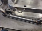
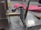
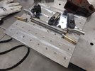
With the center support and axle tubes completed it was time to press the axle shafts into place.
rf140.jpg

When I machined the hexes down on the bolts for the axle shafts, I ensured it would be a snug fitment to help hold everything in alignment. It ended up being a nice tight fit.
rf141.jpg

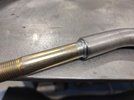
One axle shaft welded in place and ready for the next.
rf142.jpg

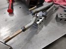
Rear axle assembly completed.
rf143.jpg

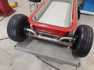
Next was to mock up the rear axle and determine angle.
rf144.jpg

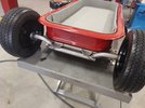
I feel like tipping the axle rearward ever so slightly was the perfect fit. Nothing but just visual preference here, as well as making sure to keep the tires far enough away from the body to prevent little fingers from getting pinched.
rf145.jpg

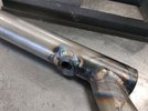
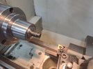
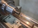
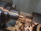
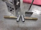
Next it was back to the lathe to machine some rear axle mounting bungs which will be welded into the rear axle at the correct angle.
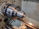
rf149.jpg

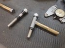
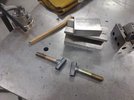
Both axle mounting threaded bungs machined.
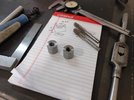
rf150.jpg

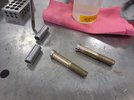
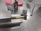
While I was at the lathe I figured I'd knock out the four body mounting threaded bungs as well. I measured the depth of the tubing so they would sit inside the tubing fully and be flush at the top.
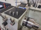
rf151.jpg

Stay tuned for more....
 

zmotorsports

Hardcore Gearhead
Vendor
Location
West Haven, UT
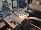
I grabbed a length of scrap plate to drill mounting holes using the DRO on the mill to ensure the exact spacing of the tabs so that it could be transferred to the rear axle.

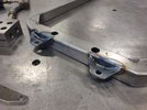
Here are the tabs bolted to the fixture plate and tack welded to the rear of the chassis once centerline was established and marked.
rf153.jpg

The rear axle was then mocked into place to see if I still liked that small 10-degree rearward angle of the axle shafts.
rf154.jpg

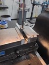
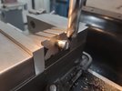
Liking that angle I clamped the rear axle into the mill vise and used the mill vise's parting line as a reference to set the 10-degree rearward leaning angle.
rf155.jpg

I then found centerline of the axle and moved half the mounting spacing each direction and bored the holes for the threaded bungs at the correct angle.
rf156.jpg

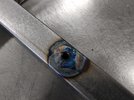
The bungs pressed in and fit perfectly at the 10-degree angle and now ready for welding.
rf157.jpg

Bungs nearly fully welded.
rf158.jpg

Tabs fully welded at this point as well.
rf159.jpg

Axle assembly and mounting tabs welded and ready to bolt together.
rf160.jpg

More to follow....
 

zmotorsports

Hardcore Gearhead
Vendor
Location
West Haven, UT
I know this had been a lot of posts/pictures but I haven't done an update to this build thread for a few weeks and it's been nice to have had the time to devote to this project lately.

Rear axle and tabs fully welded.
rf161.jpg

rf162.jpg

Rear axle cooled and bolted to the chassis.
rf163.jpg

Rear wheels installed and mocked up for reference.
rf164.jpg

Next was to weld in the threaded bungs for the body mounting. The bungs as well as the bored holes wiped with acetone.
rf165.jpg

The front body mount bungs pressed in place. The length of the bungs were spot on to result in a flush mounting surface. Almost like they were machined with that in mind. ;)
rf166.jpg

Rear body mount bungs pressed in place.
rf167.jpg

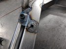
Bungs fully welded in place.
rf168.jpg

rf169.jpg

rf170.jpg


Thanks for looking and I apologize for all of the pictures at one time. Once I got back to this project I just kept full steam ahead and haven't posted any updates in a couple of weeks.

Mike
 

zmotorsports

Hardcore Gearhead
Vendor
Location
West Haven, UT
Worked on the front axle, spindles and C's last night for the wagon project.

Trying to determine the correct angle of the dangle. This has more to do with aesthetics than anything though. I settled on 15*, now to match it to the other side of the axle. I'm using .875" 4130 chromoly tubing for the axle.
rf171.jpg

The other side bent to match so the bends reside directly beneath the frame rails. Also mocked the C's up into approx. position.
rf173.jpg

I used a transfer punch just to get a visual of the angle needed for drilling and reaming the kingpin (bolt) to get the correct inclination angle. Probably way overkill for a wagon that won't see much in terms of MPH though. :rofl:
rf175.jpg

One C drilled and reamed to size for the kingpin bolt.
rf176.jpg

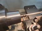
Then after contemplating what to do for the knuckle and pivot point I decided I'd use a piece of .625" x .065" wall 4130 chromoly in which I will weld a spindle onto for the knuckle. This axle will support the front wheels and pivot on the kingpin. To keep it operating smoothly I wanted to machine some bushing then remembered I had some Delrin left over from my sand drag ATV building days. I had forgotten just how nice this stuff is to machine. I machined a .500" step which will press into the vertical support for the steering knuckle.
rf178.jpg

Landed right on .500".
rf179.jpg

Next was to drill and ream the Delrin bushing.
rf180.jpg

And part it off to size.
rf181.jpg

The components for one side complete. The C, kingpin bolt, vertical support and bushings.
rf182.jpg

Other side nearing completion, all that is remaining is the last two Delrin bushings and to machine the spindles which will be welded onto the vertical support tube.
rf183.jpg


Thanks for looking.

Mike
 

zmotorsports

Hardcore Gearhead
Vendor
Location
West Haven, UT
I took a couple steps forward and a step back on the Radio Flyer wagon on Saturday.

After beadblasting the C's, I mocked them up to the axle in preparation for tack welding. I used some 1/16" TIG rod under the axle to properly space the tube in relation to the C's.
rf184.jpg

Front axle C's welded onto the axle tube.
rf185.jpg

I then mocked the axle under the front of the chassis for reference. Here is where I can see I may have made a mistake on measurements. :thinking:
rf186.jpg

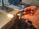
Before getting ahead of myself I figured I would go ahead and fishmouth the axle shafts and get the knuckles welded together.

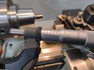
Here I am taking the axle shaft (bolt) down to .625" diameter to match the vertical tubing.
rf187.jpg

Snuck up on the angle for the fishmouth.
rf188.jpg

Notching the axle shaft for fitment to the vertical tubing.
rf189.jpg

Pretty nice and tight fitment for welding.
rf190.jpg

One machined and one to go.
rf191.jpg

Both are machined and ready to weld.
rf192.jpg

Everything wiped down with acetone in preparation for welding.
rf193.jpg

Stay tuned for more pictures....
 

zmotorsports

Hardcore Gearhead
Vendor
Location
West Haven, UT
Continuing on with the front spindles.
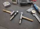
Axle shaft clamped in a V-block and the vertical tube resting on a machined block so it can be duplicated on the other side. Nice tight fitment for welding.
rf194.jpg

I blast-tacked both spindles together for a test fit before final welding.
rf195.jpg

Spindle resting on a separate V-block for final welding. This way I can easily rotate the spindle around for a full weld around the mating surfaces.
rf196.jpg

Both spindles completely welded and allowed to cool.
rf197.jpg

rf198.jpg

Next I installed the Delrin bushings and did a test fit on the axle. And unfortunately, just as I expected I made the axle just a little too wide.
rf199.jpg

While the axle was under the chassis I placed the front wheels in place and immediately didn't care for the width in which they were at. They matched the outside width of the rear tires but I just didn't like the look of it. In trying to keep with my theme I played with moving the axle around a bit and liked the position of the front tires/wheels about 2 inches further inboard. I then turned the tire to ensure it wouldn't contact the front frame rails at full turn and decided to narrow the axle 2 inches on each side.

Out came the front axle and disassembled for cutting.
rf200.jpg

I removed the 2 inches per side and then machined a couple of small sleeves to press inside the axle and outer C's for a seamless modification that once blended and sanded should be undetectable.
rf201.jpg


Thanks for looking.
 

zmotorsports

Hardcore Gearhead
Vendor
Location
West Haven, UT
Made a little more progress on the Radio Flyer wagon project.


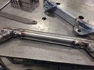
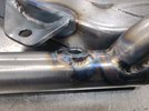
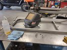
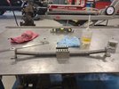
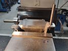
The center part of the axle clamped in the mill vise to drill through holes for Rosette welding after the sleeves are installed.
rf202.jpg

The outer ends drilled and the inner sleeves being pressed into the slight interference fit of the tubes.
rf203.jpg

Outer C's ready for welding.
rf204.jpg

One last mock up before fully pressing the ends in place and welding.
rf205.jpg

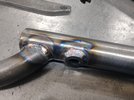
Welding completed after clamping to fabrication table to ensure no twisting would take place.
rf206.jpg

Welds knocked down and metal finished.
rf207.jpg

rf208.jpg

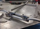
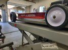
Front axle mocked under the wagon to establish placement and determine ride height. I actually think the axle is too far rearward in this photo as there is too much of the front frame horns sticking out in front of the axle. I want a little protrusion forward of the axle but this is just a bit too much.
rf209.jpg

I was able to use some V-blocks and determine ride height however. Should have just a very slight rake to it. Not too low that it will drag significantly through the grass but low enough to get the look I'm after.
rf210.jpg

Stay tuned for a few more.
 

zmotorsports

Hardcore Gearhead
Vendor
Location
West Haven, UT
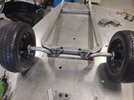
This looks much better by having the front tires moved inward on each side. Now they reside about in the middle of the rear tire placement in relation to the frame rails.
rf211.jpg

rf212.jpg

I also slid the axle forward a bit to minimize the front frame protrusion. This is about right and will still net me the rake I'm after and the clearance for the steering links.
rf213.jpg

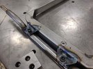
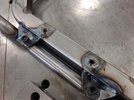
I need to build some standoffs for the axle connection. This shows the clearance I'll need for the steering linkages coming off the knuckles.
rf214.jpg

With the front axle only a couple of degrees higher than the front crossmember it will be a nice way of fabricating a connection between the two in which to make the steering pivot mount to.
rf215.jpg

I like the stance/rake and I really like this version of the front frame protrusion better.
rf216.jpg


Thanks for looking.

Mike
 
Top