Radio Flyer Project

zmotorsports

Hardcore Gearhead
Vendor
Location
West Haven, UT
I finally was able to get back to my grandson's Radio Flyer project.

I determined front axle placement and got it welded into position. Then made a template to begin work on the steering plate. This will be the base or mount for the steering at the chassis.
rf217.jpg

From here it may be a bit overkill but I figured rather than just slapping another plate on top of the base for the steering that I would go one step further and really make the steering smooth. I dug through my stash of old hardware and found a Torrington bearing in which to use for the steering. I then grabbed a small section of hydraulic rod in which to machine the bearing mount from. My goal was to create a recess in which the Torrington bearing will reside that will help hold a small amount of grease and yet still provide protection.

Here I'm facing the part.
rf218.jpg

Next, I ground a couple of HSS tooling bits into a trepanning tool for sneaking up on the recesses OD as well as the ID. Here I'm plunging to get the depth then working outward towards the target OD of 1.755" That will give me a .005" clearance from the OD of the race which is 1.750".
rf219.jpg

Next I grabbed the other HSS tool that I ground to match the depth and sneak up on the ID which was a target of .995".
rf220.jpg

The bearing measured .114" thick with both races combined so I thought I'd machine to a depth of .125" for starters then face off to the exact depth which I figured would be easier than machining exactly to depth and matching. Here is the recess completed other than a little deburring.
rf221.jpg

Test fit of the Torrington bearing and both races indicates that the bearing sits back inside about .010". I also measured one race which was .020" in thickness so I figured I would like the bearing race to stand proud approx. .008"-.012" from the face to allow the upper part to turn freely without interfering once I get everything painted.
rf222.jpg

After facing off the correct amount the bearing stands just barely proud of the recess.
rf223.jpg

Measuring the clearance I used a ground parallel and a feeler gauge to determine the actual clearance.
rf224.jpg

Landed right @ .010" clearance, perfect.
rf225.jpg


Thanks for looking.
 

zmotorsports

Hardcore Gearhead
Vendor
Location
West Haven, UT
I didn't have much shop time last night but I was able to make a small amount of progress on the steering mount.

I turned the OD from 2" down to 1.875".
rf226.jpg

I then drilled a hole to slightly undersize which will allow me to ream to size once it is welded to the bracket. Now it was time to part off the bearing housing.
rf227.jpg

Mocked up with the Torrington bearing.
rf228.jpg


rf229.jpg

Welded the bearing housing to the bracket.
rf230.jpg

rf231.jpg

Then test fitted into position one last time.
rf232.jpg


I'll ream the hole to size then once I determine the top plate material and design, I will get a shoulder bolt the correct length to hold the assembly together and weld the mounting plate to the chassis.

Thanks for looking.
 

zmotorsports

Hardcore Gearhead
Vendor
Location
West Haven, UT
Made some progress on my grandson's Radio Flyer wagon last night.

Started by making a template for the steering arms coming off the knuckles.
rf233.jpg


Cut out and a slight bend to accept the rod end and keep the tie rod below the framerail.
rf234.jpg


Tweaking the angle of the cut to make sure to have proper Ackermann angle built in.
rf235.jpg


I put the front tire/wheel on to ensure there would be no interferences.
rf236.jpg


After transferring the pattern over to some .125" P&O I drilled and reamed the holes for the 1/4" rod ends.
rf237.jpg


Then cut the arms out on the vertical bandsaw.
rf238.jpg


When making symmetrical brackets I like to bolt them together and then run them around the disc sander to ensure they are a perfect match.
rf239.jpg


One last little detail before separating the brackets is to run them parallel to the belt sander. This puts a bit nicer finish on the metal and just adds a nice finishing touch.
rf240.jpg


Here you can see how much nicer the finish is on the edges.
rf242.jpg

More pictures to follow.
 

zmotorsports

Hardcore Gearhead
Vendor
Location
West Haven, UT
Continuing on with the steering components.

Once the edges are sanded I separate the brackets for final deburring. You can still see the hard edge present in this picture.
rf243.jpg


Here's another little tip for putting a nice edge on the freshly machined or fabricated parts.

I approach the belt with the piece at about a 45-degree angle to the belt's surface. Now tip it into the belt at the bottom just barely before the top and hold it momentarily where the entire length of the bracket is being sanded evenly. If you have a rounded edge then as you work that curvature around the belt don't spend as much time in contact with the belt as you did on the long side. Work the curved edge around the belt at a quicker pace in order to keep the chamfer even all the way around. Think of it as a ratio between time spent in contact with the belt vs. surface area. The shorter sides and curves just need to be briefly touched around the belt to remove the same amount of material that a longer delay on the long sides requires in order to remove the same amount of material.

Also, be very careful when sanding a hard 90-degree corner and try to keep them facing downward, if you have a rounded edge then approach the belt with it facing upward. If you don't have any rounded edges then definitely touch off on the lower corner ever so slightly before the top or the top corner will dig into the belt destroying the belt best case scenario and digging into or grabbing your hand worst case scenario. Hope that makes sense as this little detail really adds a nice finishing touch to the edges of metal parts and once you get the hang of it becomes second nature.
rf244.jpg


Here you can see the nice chamfered edge it leaves when done properly. You can also see the rounded end has the same amount of material removed and the size of the chamfered edge is consistent.
rf245.jpg


I then marked the same distance on each bracket to create a slight bend and clamped in the brake.
rf246.jpg


Bends done.
rf247.jpg


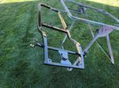
I rigged up a quick fixture in which would allow each steering knuckle to accept the steering arm at the same height and angle and proceeded with a quick blast tack on each corner. In this picture you can also see where I made the steering arm just long enough to also capture the small spacer in which I added to space the wheel out away the proper amount. By making the steering arm wide enough I was able to capture this all into the weld and incorporate the spacer into the knuckle.
rf248.jpg


Double checking to make sure both angles were identical.
rf249.jpg


Fully welded the steering arms onto the knuckles.
rf250.jpg


Both knuckles completed.
rf251.jpg


On the opposite side of the steering arm I ran a short stitch weld to tie the spacer into the main body of the knuckle. No real need to do this I just thought it would look better to have some weld opposite the steering arm to hold the spacer to the main body. I just did a short autogenous weld here.
rf252.jpg


That completed the steering knuckles for the Radio Flyer wagon.
 

zmotorsports

Hardcore Gearhead
Vendor
Location
West Haven, UT
I have a rather large picture dump which will be several posts from Saturday's work on the Radio Flyer project.

The center crossmember was drilled slightly undersize until I married the plate to the pivot bearing housing. I then reamed them both at the same time to .500" before tacking in place.
rf253.jpg


Aligning and mocking into position.
rf254.jpg


Tacked in place.
rf255.jpg


Next was to begin designing the top steering plate.
rf256.jpg


And to design and fabricate the handle connector mechanism. This handle will be removable with a quick release pin. The first wagon I built 30 years ago did not have such an option and the handle would be in the way when transporting and I always worried it would smack the side of the truck bed so I opted to make this one quickly removable for transporting.
rf257.jpg


The plate was measured and cut out before drilling and reaming the .250" diameter pin holes. I had to make the plate wide enough to barely catch the ball detents on the pin yet not too wide.
rf258.jpg


Ears bent up on the pan brake.
rf259.jpg


Pin has a nice tight fitment and the detents just clear the other side.
rf260.jpg


Then a quick trip to the lathe in which to machine the center section and ream a .250" diameter bore through the middle.
rf261.jpg


Everything fits together very nicely.
rf262.jpg


Stay tuned for more.....
 

zmotorsports

Hardcore Gearhead
Vendor
Location
West Haven, UT
Continuing on with the Radio Flyer project.

Continuing on with the design of the steering plate and how the handle will connect. At first I thought I'd weld a couple of tabs onto the plate and have the center section as part of the handle. But then I changed my mind when I considered the hard edges from the tabs right where my son would be grabbing it to lift it into the truck so I figured the bored section would be better on the steering plate the and tabs on the removable handle.
rf263.jpg


After a few iterations and modifications and I was happy with the design, the pattern was transferred to some .125" plate.
rf264.jpg


After being cut out the radii were ground and smoothed out along with a slight chamfer on the edge.
rf265.jpg


Getting closer.
rf266.jpg


The center pilot hole was drilled and the holes for the tie rods were drilled and reamed. The rod is used as a placeholder for the tie rods as I have some .375" 6061 aluminum rod coming tomorrow. However, after looking at it I feel like I need to keep the tie rods on top of the steering plate so they match the outer knuckles.
rf267.jpg


So back to the brake to form a step in the rear of the steering plate.
rf268.jpg


Perfect. Now the tie rods will sit on top of the components and be level throughout the steering system.
rf269.jpg


And while I was at it I thought I'd make one more trip to the brake and create a small turn-down to the front where the pivot will be mated.
rf270.jpg


I have a .5" shoulder bolt coming tomorrow that has a .750" shoulder. I measured the stack of components at it lands right at .700" thickness. The Torrington bearing stands .010" proud of the housing so I should need to machine a .040" shim for the underside of the steering plate to bring it right to the clamping range of the shoulder bolt.
rf271.jpg


Pivot welded to the steering plate.
rf272.jpg


Stay tuned for more.....
 

zmotorsports

Hardcore Gearhead
Vendor
Location
West Haven, UT
Continuing on.

Before final welding of the steering crossmember I drilled a .062" hole near the end. This is critical when welding tubing as the pressures build up internally in the tubing from the heat generated during the welding process and if the pressure is not allowed to be relieved it will blow out right as the weld is being completed and make everything look like shit. When joining tubes I generally drill these holes under the area where the next tube will join so they are always vented back to atmosphere. However, in this instance where the holes around the rest of the chassis have been covered already I drilled a couple of small holes near the end of each tube. I then weld the joint close to where the hole is drilled and stopped. I let the heat and pressures dissipate while I do something else and then come back and weld the last quarter or half inch and close up the hole as I finish the weld. The tube is just large enough that the pressures won't build up fast enough for the last quarter inch or so of weld and I'm able to finish it out smoothly without blowing the molten puddle out.
rf273.jpg


One more mockup the steering to check for interferences. I measured the length between the tie rod holes in the straight position and then at the turned position for reference.
rf274.jpg


Next I thought I'd fabricate some mounting tabs for the lights. I found these from a motorcycle parts supplier to simulate the large King Bee headlights typically found on a 32' roadster. These will not be powered of course and are being installed purely for aesthetics. Tabs cut out of cardboard and transferred to some .095" plate.
rf275.jpg


After mounting holes were drilled and reamed they were bolted together for metal finishing. The heavy grind marks from the 60-grit disc going perpendicular to the mounting tabs.
rf276.jpg


Shapes are symmetrical.
rf277.jpg


Then the mounting tabs were turned parallel with the 120-grit sanding belt for the smooth finish.
rf278.jpg


After separating the tabs and the one in the foreground has been chamfered compared to the one in the background with the hard edges remaining.
rf279.jpg


Tabs welded into position at the front of the chassis. This step was chosen to be done before the center crossmember to take advantage of the vent holes previously drilled to allow the pressures to escape.
rf280.jpg


rf281.jpg


Overview of the front end before final welding of the crossmember.
rf282.jpg


More to come...
 

zmotorsports

Hardcore Gearhead
Vendor
Location
West Haven, UT
The last of the pictures from Saturday's work on the Radio Flyer wagon project.

Now to mock the headlights into position....
rf283.jpg


..and check one final time for any interferences.
rf284.jpg


Everything looked good so the steering crossmember was fully welded into place. The last quarter of an inch or so was left and allowed to cool before completing and closing up the vent holes.
rf285.jpg


rf286.jpg


rf287.jpg


Steering mocked into place one more time.
rf288.jpg


Thanks for looking. The wagon project is getting very close to having the fabrication work completed then it can be broken down for paint & body.

I think I am going to try something different with this chassis however. It's been about 20 years since I built my last street rod chassis and with the street rods that I built in the past I mudded and smoothed the welds for aesthetics. They turned out awesome and netted me some nice trophies and magazine exposure but also much of that decision was due to the fact that my welds were, well let's just say less than desirable to look at. They were strong but not as pleasing to the eye as I would have wished. In fact, after my last street rod chassis in 1999 is when I made the decision to take a deeper dive into welding and fabrication and work on fine tuning my skillset. I also got into a bit of a battle with the NHRA during a couple of events when I decided to race mine as they like to see the actual welds. My local track was less concerned but coincidently, back in the 90's my car was just under the threshold requiring such inspections so I slipped through the cracks.

That being said, when I started building sand drag quads and then sand rails, I had studied much of the literature from the NHRA and followed the guidelines and requirements for welded tube joints and therefore when I built those chassis I refrained from mudding and smoothing the welds. My welds had been improving by that time and to be honest, once covered with a sealer, paint and clear the ripples were visible but didn't look all that bad.

I feel my welds are a bit better than even 10 years ago so for that reason I think I am going to leave the welds raw on this chassis and just let the sealer, paint and clear fill in where they do. To be honest, I actually like seeing nicely done welds when I look at street rods chassis vs. smoothed and mudded welds these days, so I hope they turn out as well as I am imagining.

Thanks for looking.
 

zmotorsports

Hardcore Gearhead
Vendor
Location
West Haven, UT
Made a little more progress last night.

My son came over to service his wife's car so while I had him available I threw the tires/wheels on the wagon and mocked it up to measure for handle length.

I think it has a nice stance with just the right amount of rake. Low enough to look kool, yet not so low it will be hard to pull through the grass.
rf289.jpg

rf290.jpg

Once handle length and angle of the dangle was determined, I grabbed a short piece of 1" 6061 aluminum for the handle grip. I measured hand width and determined a size then chucked it up in the lathe and began facing the part.
rf291.jpg

Then drilled and tapped for a 3/8"-16 thread.
rf292.jpg

Then turned down just about .010" to get a nice finish.
rf293.jpg

And to give it some texture I put a few small grooves in the grip. Then flipped it around and did the same to the other end.
rf294.jpg

Ran some white Scotchbrite over the part.
rf295.jpg

Complete for the most part. I will apply a bit of aluminum polish before final assembly.
rf296.jpg


With the grip completed and I have my overall width, I will next fabricate the handle end end that the grip will bolt into then the handle can be completed. I dug through my fasteners and found a couple of ARP stainless steel 12-point bolts that I feel are appropriate for the build.

Thanks for looking.
 

zmotorsports

Hardcore Gearhead
Vendor
Location
West Haven, UT
Made quite a bit of progress on the Radio Flyer project on Saturday.

The last of my misc. parts and materials arrived from McMaster Carr late last week so I was able to get the tie rods completed. Used some 6061 aluminum rod.
rf321.jpg


My left hand tap also arrived so I was able to drill & tap the ends.
rf322.jpg


Cut to length, faced and some Scotchbrite ran over them.
rf323.jpg


Mocked into place to determine where to put the steering stops.
rf324.jpg


Looks like about 20-degrees will keep the knuckles off the paint.
rf325.jpg


Allowing just a little bit of wiggle room for paint mil thickness.
rf326.jpg


That should work.
rf327.jpg


Stops welded under the steering pivot plate to keep them concealed.
rf328.jpg


rf329.jpg


Testing the stops.
rf330.jpg

More pictures to come...
 

zmotorsports

Hardcore Gearhead
Vendor
Location
West Haven, UT
Just enough clearance to keep the paint from contacting itself at full lock.
rf331.jpg


Steering stops fully welded.
rf332.jpg


Moving on to the handle bumpstop. Tacked in place for test fitment.
rf333.jpg


Receiving end mocked into place and marked.
rf334.jpg


Fully welded out.
rf335.jpg


rf336.jpg


Front end mocked up one final time to check for interferences as well as set the body in place.
rf337.jpg


rf338.jpg


rf339.jpg


rf340.jpg


That's it as far as fabrication goes. Time to blow it apart for paint prep.
 

zmotorsports

Hardcore Gearhead
Vendor
Location
West Haven, UT
Wagon blown apart and separated into those items to be painted.
rf341.jpg


And those not to be painted and a few will need some polishing.
rf342.jpg


Ran over the entire chassis with some 80-grit on a DA sander as well as wire wheeled the welds in preparation for the epoxy primer.
rf343.jpg


Paint supplies at the ready. SPI Epoxy Primer will be shot first.
rf344.jpg


One final wipe with Wax & Grease Remover before hanging outside to be sprayed.
rf345.jpg


Prepped and ready for epoxy primer.
rf346.jpg


Epoxy primer applied.
rf347.jpg


rf348.jpg


rf349.jpg


The primer laid down pretty nicely.

Thanks for looking.
 

Attachments

  • rf347.jpg
    rf347.jpg
    351.6 KB · Views: 2

zmotorsports

Hardcore Gearhead
Vendor
Location
West Haven, UT
Started off with some blocking of the SPI epoxy primer last night.
rf351.jpg


rf352.jpg


I have a couple of minor low spots on the frame rails, noted where the black primer was not fully sanded.
rf353.jpg


After everything was sanded with 180-grit it was blown off then wiped down in preparation for a skim coat of glazing filler in certain areas.
rf354.jpg


Ready to mix up some glazing filler.
rf355.jpg


After applying the glazing filler and while waiting for it to cure enough to sand I took some components to the blasting cabinet and gave them a once over in preparation for primer and paint.
rf356.jpg


Sanded the several spots of filler down smooth and blended in to surrounding areas.
rf357.jpg


rf358.jpg


rf359.jpg


Coming along nicely. Underneath completed and flipped the frame upright with only a couple small dimples or low spots to apply a bit of glazing filler.
rf360.jpg


That was it for last night. It's getting close for another round of epoxy primer.

Thanks for looking.
 

zmotorsports

Hardcore Gearhead
Vendor
Location
West Haven, UT
Finished up the glazing of a few low spots last night, I hope that should be all at least.

Here's a little trick if you only have a pinhole or some small imperfection that you want to fill without leaving much thickness or buildup to have to sand down, use a razor blade as the applicator. Works excellent for those small spots.
rf361.jpg


Had a very small "dimple" right where the front crossmember end cap was welded on that needed to be filled and the razor blade worked perfectly to apply a very small controlled amount which was easily removed afterwards with a few swipes of some 180-grit paper.
rf362.jpg


A couple of other areas that needed just a skim coat more glaze.
rf363.jpg


After curing the glaze was sanded down. Then the chassis was blown off with compressed air, wiped with Wax & Grease Remover, then hung to be sprayed with another few coats of SPI's Epoxy Primer.
rf364.jpg


Hung and wiped with a tack cloth.
rf365.jpg


A light coat was first applied as a "tack coat" then a medium wet coat followed by a couple more medium wet coats with about 10 minutes or so between coats. I was trying to hurry just a bit as the clouds were really thickening after mowing the lawn and I was worried I wouldn't make it.
rf366.jpg


After several coats of epoxy primer were applied and ready to have the wife help me haul it back into the shop.
rf367.jpg


rf368.jpg


rf369.jpg


Overall I am quite pleased with how the primer laid down and I should just be able to wet sand it with 400-grit and go to sealer and paint.

Thanks for looking.
 
Top