
what are you concluding here?Looking at the brake schematic Alldata appears to contradict itself. Or maybe they are showing this schematic in the opposite of it normal position (which GM does on occasion) and they did not note it.
View attachment 176307
You can't have pins C and D both used in a normally open and a normally closed switch. This makes sense according to this diagram as it show only one switch that controls the TCC and the brake input.
You are using an out of date browser. It may not display this or other websites correctly.
You should upgrade or use an alternative browser.
You should upgrade or use an alternative browser.
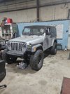
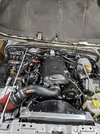
LS Swap 5.3 4I60e in 04 Jeep LJ.
- Thread starter mdbs14
- Start date
what are you concluding here?
What do you mean if it switches the other way? What other way? Are you still supporting the 0v, 12v on brake pressed theory, or is that out at the window??Wire it in with the relay in such a way that it will be easy to bypass the relay if it switches the other way. Try it and see what happens?
The relay is wired in such a way that I get 12v with key on, and 0v when brake is pressed, which I though was the correct way on gen 3 ls until I read from a post above that gm wants the opposite (0v, 12v brake press) of that. Is that still valid, or is Alldata showing something else?
I can understand wiring it without the relay if I had cruise control, I just don't understand the 0v, 12v brake pressed on a tcc.
I hope others can tell us how they have theirs wired.
I had it already wired the way i illustrated, and haven't touched it. It will stay like that if it's not wrong.It’s probably time to just make a decision based on all the information you’ve received and run with it.
Thank you for all your input on this, much appreciated.
glockman
I hate Jeep trucks
- Location
- Pleasant Grove
Nice work man.
Thank you all for all the help with this project.Nice work man.
glockman
I hate Jeep trucks
- Location
- Pleasant Grove
I had Ricks muffler in Orem do mine. Jesse used two mini cat's and I think I'm running a magna flow. 2in, single 3" out and I love the sound. No rasp, crackle or pop and it's not obnoxiously loud.Next on my to do list is the exhaust. What are you guys using for Cats converters, and tubing to make the exhaust?
I am in MA, dont think I can use Ricks Muffler, I suppose they need the car there in order to make the exhaust. What are the mini cat'sI had Ricks muffler in Orem do mine. Jesse used two mini cat's and I think I'm running a magna flow. 2in, single 3" out and I love the sound. No rasp, crackle or pop and it's not obnoxiously loud.
glockman
I hate Jeep trucks
- Location
- Pleasant Grove
These are the mini cats, one on each bank before the muffler.

Dakota digital makes a shift indicator. They are kind of pricey for what they are. I found the logic truth table for the 4L60E neutral safety switch and considered using a logic control chip to feed a simple digital readout but never got around to it.
Dakota digital makes a shift indicator. They are kind of pricey for what they are. I found the logic truth table for the 4L60E neutral safety switch and considered using a logic control chip to feed a simple digital readout but never got around to it.
- Location
- West Haven, UT
I also need some sort of Gear selector indicator light for my state inspection. They want to see what gear (P, N, D) its in when shifting. What are some options out there?
Does it have to be a light or can it be part of an aftermarket shifter?
I like those mini cats, where to buy thm?These are the mini cats, one on each bank before the muffler.
View attachment 176865
Dakota digital makes a shift indicator. They are kind of pricey for what they are. I found the logic truth table for the 4L60E neutral safety switch and considered using a logic control chip to feed a simple digital readout but never got around to it.
Yes, the Dakota one is $$$$. I did see one that uses the OBD2 and displays on an android app.
Will have to ask, but I know they want to see some sort of indicator light of what position the shifter is in displayed somewhere around the dash.Does it have to be a light or can it be part of an aftermarket shifter?
I was thinking of doing it myself once I source a good pipe bender.If doing the exhaust your self the magnaflow heavy metal universal cats are a good solution. I've used them on a couple projects with no issues.