- Location
- West Haven, UT
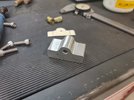
Continued on with the machining for the blocks last night.
I know this is kind of crazy the amount of time I am spending on these things and waaaaayyyyyy overkill just to cure a squeak/creak. However, I have not used my rotary table a lot over the years and I thought seeing as how I have a lull in side jobs this week that I would try to sharpen my skills a bit and get some practice. Plus making chips is kind of fun. :bounce:
My Phase II rotary table was purchased many years ago at an estate auction and about the only thing I used it for over the years was to machine elongated slots in ignition timing plates for advancements/adjustments on various snowmobiles and ATV's when we were building a lot of 2-stroke engines for powersports equipment. Last year I tore it apart to clean it up as the grease was so hard it did not operate very smooth at all. After a major cleaning and polishing up some bores and shafts this thing works as smooth as silk now. The rotary table turns so easily and advances the table much more fluid than it ever did in the past.
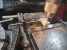
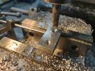
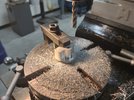
I started by using a 3/8" end mill to create the two radii around the lower block.
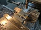
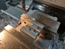
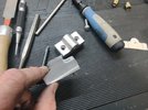
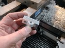
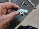
I then went to the vertical bandsaw and cut the two blocks apart before the next processes.
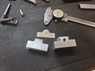
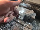
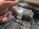
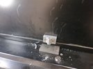
This is also overkill for a non-critical part but I wanted to play with my corner rounding end mills and put a radius on each of the two outer corners. More practice.
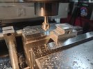
I made this "quick setup tool" for aligning the rotary table several years ago after watching one of Tom Griffin's YouTube videos on Tom's Techniques. I machined a Morse Taper #3 on the big end and used a cut-down shoulder bolt for the shaft. I put it in a collet in the mill quill and then align it with the rotary table so it goes in/out easily and the taper auto-centers the rotary table in relation to the quill centerline. I had to dig through my machining box to find it. I should probably keep it more readily available when I put it away after this project.
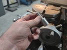
Centering slug in place in the center of the rotary table.
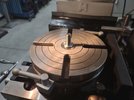
Centering tool in 1/2" collet then the rotary table centered under it for easy in/out sweep of the quill then bolt/clamp the rotary table down to the mill table and the X and Y axis are zeroed out on the DRO.
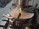
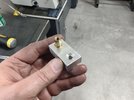
Next I used a .250" gauge pin to center the hole from the block over the center of the rotary table. This ensures the radius will be equal around the pin bore.
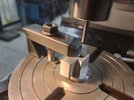
Make certain that the part is in line with either the X or Y axis or you will be moving the radius off the center pin bore at an angle.
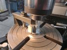
Once the radius is determined, move the table away from the center position the proper distance PLUS half the cutting tool diameter. I also go a bit more so I have material for a final or clean up cut.
More pics to follow......
I know this is kind of crazy the amount of time I am spending on these things and waaaaayyyyyy overkill just to cure a squeak/creak. However, I have not used my rotary table a lot over the years and I thought seeing as how I have a lull in side jobs this week that I would try to sharpen my skills a bit and get some practice. Plus making chips is kind of fun. :bounce:
My Phase II rotary table was purchased many years ago at an estate auction and about the only thing I used it for over the years was to machine elongated slots in ignition timing plates for advancements/adjustments on various snowmobiles and ATV's when we were building a lot of 2-stroke engines for powersports equipment. Last year I tore it apart to clean it up as the grease was so hard it did not operate very smooth at all. After a major cleaning and polishing up some bores and shafts this thing works as smooth as silk now. The rotary table turns so easily and advances the table much more fluid than it ever did in the past.
I started by using a 3/8" end mill to create the two radii around the lower block.


I then went to the vertical bandsaw and cut the two blocks apart before the next processes.

This is also overkill for a non-critical part but I wanted to play with my corner rounding end mills and put a radius on each of the two outer corners. More practice.

I made this "quick setup tool" for aligning the rotary table several years ago after watching one of Tom Griffin's YouTube videos on Tom's Techniques. I machined a Morse Taper #3 on the big end and used a cut-down shoulder bolt for the shaft. I put it in a collet in the mill quill and then align it with the rotary table so it goes in/out easily and the taper auto-centers the rotary table in relation to the quill centerline. I had to dig through my machining box to find it. I should probably keep it more readily available when I put it away after this project.

Centering slug in place in the center of the rotary table.

Centering tool in 1/2" collet then the rotary table centered under it for easy in/out sweep of the quill then bolt/clamp the rotary table down to the mill table and the X and Y axis are zeroed out on the DRO.

Next I used a .250" gauge pin to center the hole from the block over the center of the rotary table. This ensures the radius will be equal around the pin bore.

Make certain that the part is in line with either the X or Y axis or you will be moving the radius off the center pin bore at an angle.

Once the radius is determined, move the table away from the center position the proper distance PLUS half the cutting tool diameter. I also go a bit more so I have material for a final or clean up cut.

More pics to follow......

