General Tech What did you work on Today?

Hickey

Burn-barrel enthusiast
Supporting Member
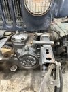
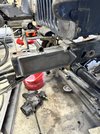
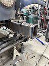
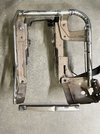
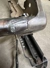
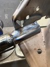
More work on Todd’s Jeep. Mounted the steering box in its new spot and started plating the frame. I moved the radiator up 1.5” to clear the input on the steer box.

IMG_7128.jpegIMG_7131.jpegIMG_7132.jpeg

I need to source 3’ of 2x4 .188 tube to build a new bumper. We were going to use a Motobilt bumper, but it’s just not gonna work with the front axle stretch.
 

JeeperG

Well-Known Member
Location
Riverdale
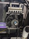
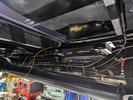
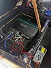
Got the transmission cooler mounted, plumbed and wired (pics are before wiring done) not much real estate up front so under the bed it is.
1000005229.jpg

1000005230.jpg
Did some pressure testing on the cooling
1000005231.jpg
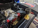
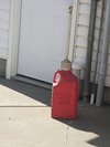
Put some antifreeze, power steering fluid and 5 gallons of pump gas. Filler neck was leaking on the truck, see if we can fix that.
1000005232.jpg
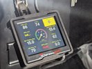
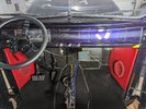
Most of the wiring seems to be working, park brake is not, control box has been sent back to e-stopp. Fuel gauge isn't reading on instrument cluster? Fired it up a few times and ran rich with the sniper getting some bouncing readings. Might just be interference? We are rerouting the wire for the touchscreen as it was ran pretty close to the coil, double checked TDC, all the wiring and timing, gonna get a little better timing light for this set-up and check it again.
1000005236.jpg
 

XJEEPER

Well-Known Member
Location
Highland Springs
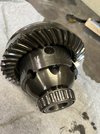
I’ve been trying to track down the low speed rhythmic clunk clunk sound in my front end to no avail.
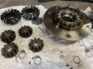
I finally pulled the ARB, hoping for worn/broken spider gears as the cause.

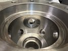
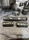
No smoking gun here, the wear is all uniform for a 16yr old diff, center pin diameters measure .0688, spider inner diameter measures .0690 on all 4. No visible wear or play in the side gears. Thrust washers are worn but pretty consistent.
R&P are only a year old (6000 miles) as are all the diff bearings, seals and axle u-joints. Backlash is in spec and contact patch looks great.

I rolled the dice today and ordered a new spider/side gear kit and thrust washer kit and I’m crossing my fingers that these new parts solve the issue.

IMG_0977.jpegIMG_0979.jpegIMG_0981.jpegIMG_0983.jpeg
 

XJEEPER

Well-Known Member
Location
Highland Springs
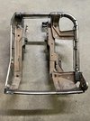
If you've owned a Jeep Cherokee, you know that it's only a matter of time until the bucket seat frames fail. Driver side seat base failure is more common than passenger side, due to frequency of use, but the same inferior welding process is used on both by the factory. I've repaired several of these over the years for other XJ owners, at much lower mileage, so I'm fortunate that mine survived for 238k miles before fully letting go.


IMG_0984.jpegIMG_0986.jpegIMG_0988.jpegIMG_0985.jpegIMG_0987.jpeg

Once the seat is pulled out of the rig and the seat cushion unbolted from the seat back and the cushion removed (less than 10min job), it's pretty easy to realign all of the seat frame pieces and weld them back together and laying down more welds at the stress points will prevent this issue from reoccuring.
IMG_0989.jpegIMG_0991.jpeg
Back together and better than new.

IMG_0995.jpeg
 

JeeperG

Well-Known Member
Location
Riverdale
Fired up the big block last weekend but we are getting issues with the sniper, we have checked and rechecked everything multiple times and still haven't figured it out, is the sniper itself faulty? Are we getting interference issues? Do I need to try a different distributer or plug wires? I have no idea yet, did some data logging, we'll get that to Holley and talk to some techs some more but this shouldn't be that hard and now I'm getting frustrated.

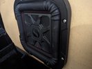
Got the e-stopp fixed, had a faulty control box and also tossed in all the speakers and adjusted amp settings, tested the speakers.
1000005332.jpg
Not much space in this cab
1000005353.jpg
Should be plenty loud for me.
1000005334.jpg
 

zmotorsports

Hardcore Gearhead
Vendor
Location
West Haven, UT
I've been away from the forum for a bit as life has gotten busy. Last year I promised way too much side work out and my list got out of hand, so I had to put a stop to adding to the list until I got caught up.

To add insult to injury, I have a bunch of personal projects that I am trying to address this spring such as the coach needing new tires and some routine maintenance before our RV'ing season begins. In addition to all that, I decided to attack the house's attached garage. When we first moved in 7 years ago the plan was to get the shop built, set up and moved in before finishing the unfinished attached garage. Life got away from me and it has now been 7 years and I still don't have a finished garage. My nephew quit his job to pursue his own dream of being a general contractor so I figured I would have him do the finishing work on the garage but that took a couple weeks of me getting it ready to him. I had some electrcial outlets I wanted to add plus some networking conduit from the house to the shop's connection and then reinforcing the landing and closing in a small area all before he could begin mudding and finish work.

That is well on its way now so I figured I would knock out a quick repair job over the weekend.

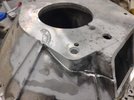
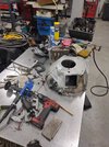
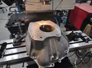
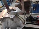
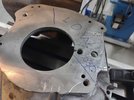
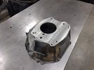
A client brought me a bell housing from an early 80's Jeep J20 project that he and his son are working on. The bell housing had a crack in it that needed to be welded.


Thought I'd post up some rather lengthy posts pertaining to the Jeep J20 bellhousing repair that I did over the weekend and how I usually go about such a repair.


Turned out to be a pretty easy welding job, but quickly changed into a more in-depth repair after the welding was completed.

Starting with a dip in the solvent tank.
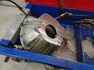
bh1.jpg


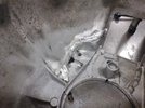
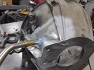
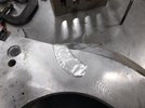
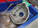
Once the grease and grime were removed it was evident that this bellhousing had been repaired at least twice before, or once but in two different locations. After I sent some pictures to the owner and a phone call requesting permission to proceed with no guarantee (but high confidence), I was given the go ahead to perform the repair.
bh2.jpg


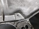
One of the previous welds and the current crack.
bh3.jpg


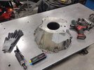
Tools at the ready and glad I decided to use my die and penetrant to determine the end of the crack as it was well up into the transmission mating surface and about an inch further than originally thought. Also put the bell housing in the media blasting cabinet to clean the area immediately around where the repair will be performed.
bh4.jpg


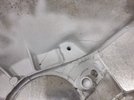
Stop drilled a hole at the end of the crack.
bh5.jpg


Inside was V'd out using a rotary bit coated with tube wax.
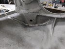
bh6.jpg


Then a thorough cleaning with acetone and wire brush. If you look closely, you can also see the slight discoloration from the acetone noting some heat would be required to bake the area clean.
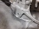
bh7.jpg


I've been using 4943 TIG rod for the past couple of years now and have really come to like this rod. Stronger than standard 4043 yet with a bit more silicone so it wets out nicely and flows well, actually a bit better than 5356 on cast.
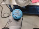
bh8.jpg


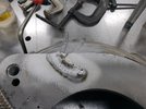
With the welder setup and at the ready I hit the area with a small torch. This not only preheats but also bakes out some of the last bits of residue from the oil/grease and solvent. Cast aluminum is dirty enough by nature but this at least aids in removing as much as the exterior contaminants as possible.
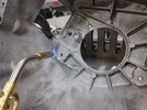
bh9.jpg


I shoot for around 250-350 degree to cook as much crap out as possible and preheat the parts, mainly in the thicker areas.
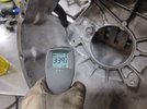
bh10.jpg


Stay tuned for more.
 

zmotorsports

Hardcore Gearhead
Vendor
Location
West Haven, UT
Continuing on.


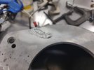
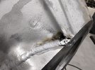
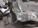
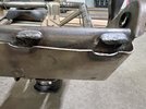
Here is the commencement of the weld. You can see the small pop marks from the impurities from the casting coming out while the puddle is molten. The trick with welding cast aluminum is not to just light up, and get to dipping rod. You won't get a pretty weld with most cast aluminum. What you are actually trying to do is heat the aluminum with the arc and get the dirt and crap from the casting to float to the top of the molten puddle. Then you kind of push the puddle forward while trying to keep that crap floating on the surface and just push it forward. Almost think of it as brazing rather than trying to get all of the parent material molten. Then wire wheel or brush the black soot which are the contaminants, and rinse and repeat.
bh11.jpg


Here I actually bathed the arc over the crack without adding filler and without actually getting a molten puddle to form. I am just trying to use the cleaning action of the AC arc to draw out whatever I can from the casting. Then wire brush it away and then go back in with the arc and begin welding.
bh12.jpg


You can see here that the majority of the weld bead is porosity free and the toes have actually wet in fairly well. This is the result of getting the crap from the casting to float and then mechanically removing it with a stainless steel brush or wheel before proceeding. There are still a couple of small pop marks but much less than had I just started the arc and tried to pound filler rod into the groove.
bh13.jpg


This shot better reveals the black impurities that have been forced out ahead of the puddle and can then be brushed away. I also used a relatively low balance to use the cleaning action of the AC wave.
bh14.jpg


Same weld bead after a quick hit with the wire brush.
bh15.jpg


With the transmission mounting face area welded, I can focus my attention on the area back towards the clutch fork opening, but more cleaning will be necessary before proceeding.
bh16.jpg


Good place to stop for the night.
bh17.jpg


Stay tuned.
 

zmotorsports

Hardcore Gearhead
Vendor
Location
West Haven, UT
This brings me to Saturday morning.

Out to the shop with coffee in hand to continue where Ieft off the night before.

For starters, on Saturday mornings when powering on the air compressor and opening the ball valve, I drain the tank into a gallon jug I keep next to it on the floor.
bh21.jpg


I then heated up the next area to be welded. This area was quite thick being a mounting point for the transmission, so a bit more heat was required.
bh22.jpg


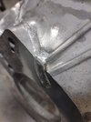
But this area welded out very nicely. You can see the cleaning zone along the weld bead and how well the toes wet in. The small amount of impurities were pushed out at the end as they had been floating along on the surface of the molten puddle. Also note the very small amount of pop marks from impurities forcing their way out along this area. More than likely because they had been pulled out on the inside of the crack so when I V'd this side out I actually hit good aluminum that was deposited from the backside.
bh23.jpg


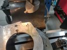
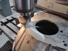
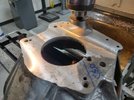
I built this area up a bit knowing I was going to have to file it down. At this point I actually decided that rather than filing the bead down that I would just clamp it to the milling machine table and know it down flush with an end mill.
bh24.jpg


I did remove some of the bead profile along the clutch fork opening as this area usually has a boot or bellows around the perimeter and I wanted it to be able to close up the opening.
bh25.jpg


Then the radius filed slightly.
bh26.jpg


One last shot of the exterior of the bell housing up to the transmission mating surface.
bh27.jpg


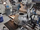
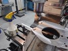
Clamped to the mill table and ready to machine down the weld bead to flush.
bh28.jpg

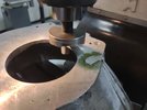
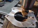
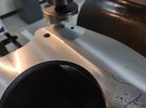
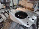
First pass seemed to take it down evenly. Rather than use an end mill I opted to grind a tool steal blank to be used in my large flycutter head as this should produce a slightly nicer finish.
bh29.jpg


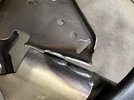
It was after this pass that I knew something was amiss. I noticed that the bead profile was taken down to flush on one side of the bead but still stood proud on the other. This had me concerned.
bh30.jpg


Stay tuned for more.
 

zmotorsports

Hardcore Gearhead
Vendor
Location
West Haven, UT
Continuing on.

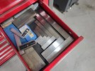
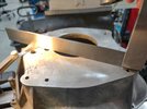
I reached for my larger machinist square.
bh31.jpg

Measured side to side and found there was quite a variance.
bh32.jpg

bh33.jpg

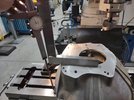
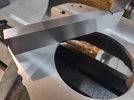
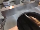
I then laid the square across the transmission mounting surface and noted a .030" difference from side to side.
bh34.jpg

bh35.jpg

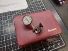
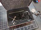
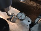
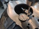
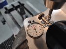
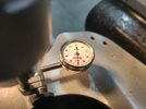
To confirm my rough measurements I grabbed my Starrett test indicator and set up in the quill.
bh36.jpg

bh37.jpg

After confirming my gut feeling about the surfaces not being parallel I made another call to the owner. I was given the go ahead to proceed being this far in.

I explained that I felt this was the reason he was continuing to have issues with cracks on this particular bell housing. With the bell housing being mated to the back of the engine it would mean that when the transmission was bolted up to the bell housing two things would happen. First that without the two machines surfaces being parallel that the transmission would be trying to pull that area up to meet it and pull the transmission down towards the low spot resulting in some extreme forces on the cast aluminum bell housing. It would also mean that it was unlikely that the transmission input shaft was parallel with the engine crankshaft and this could create some undue forces with the clutch assembly as well.

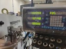
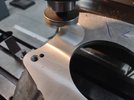
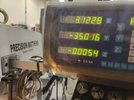
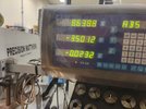
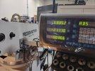
I had to turn the bell housing on the mill table to ensure I could reach across the entire surface with the flycutter, I then raised the table to touch off and zero'd the DRO on the highest point of the transmission mating surface.
bh38.jpg

bh39.jpg

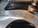
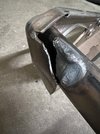
I marked for reference the low area of the transmission mating surface.
bh40.jpg


Stay tuned for more.
 

zmotorsports

Hardcore Gearhead
Vendor
Location
West Haven, UT
Continuing on.

I started with a rather light cut to get my travel speed and cutter speed dialed in for a nice finish.
bh41.jpg


This is a good indicator if your mill's head is trammed in correctly. No detectable ridges between passes.
bh42.jpg


With one light pass complete and feeds and speeds dialed in it was time to proceed.
bh43.jpg


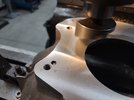
Now it was time to let the flycutter eat.
bh44.jpg


bh45.jpg


Beautiful finish being left behind.
bh46.jpg


Continuing to raise the table about .008" or so at a time. I probably could have gone .010" plus but I liked the surface finish so I just continued to move through the process conservatively.
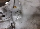
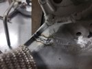
bh47.jpg


After about 3 passes it was looking decent with .023" removed.
bh48.jpg


The area of the low spot was diminishing nicely.
bh49.jpg


Nearly complete and ready for the final pass.
bh50.jpg


More to follow.
 

zmotorsports

Hardcore Gearhead
Vendor
Location
West Haven, UT
On to the last of the pictures from the repair.


Last pass.
bh51.jpg


Total removed was .036" from the transmission mating surface. That small of an amount shouldn't have any effect on the distance between the engine and transmission to negatively affect clutch engagement.
bh52.jpg


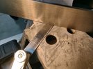
Another check with the machinist square reveals a nice flat and true surface.
bh53.jpg


In all directions.
bh54.jpg


To confirm I installed my Starrett test indicator back into the quill and rotated around the machined surface.
bh55.jpg


bh56.jpg


bh57.jpg


bh58.jpg


With being very pleased with how true and parallel the two mounting surfaces are now, I can clean up the welding table and begin breaking the mill setup down.
bh59.jpg


There are a few porosity pop marks from the previously repaired area(s). I feel good about the area that I repaired but didn't want to touch the areas someone else repaired.
bh60.jpg


All in all, another repair that I feel pretty good about and am pleased with the results.

Thanks for looking.
 

zmotorsports

Hardcore Gearhead
Vendor
Location
West Haven, UT
Wow! Good stuff Mike!

Thank you.


Mike! That's really great thanks for sharing. I'll have to try that different filler rod. Will your share your power and balance settings with me as I tend to do a lot of cast aluminum repairs on engine cases as well.

Thanks.

Balance was set to 60% EN to allow a bit more cleaning and I used 80 Hz for the majority of the repair. I bumped it down to 70Hz when doing the thicker portion where the transmission bolts up but the majority of it was @ 80 Hz. This puts a little more heat into the part that a higher frequency.
 

zmotorsports

Hardcore Gearhead
Vendor
Location
West Haven, UT
@Gravy , seeing as how you specifically mention motorcycle cases I thought I'd share my experience from all the years of welding them during my career.

Most of the time engine cases being a little thinner I will use a higher frequency between 90 to 120 Hz. Also, especially with the Japanese cases where they are a bit better quality casting, I will be in the 64% to 66% EN range as they require a little less cleaning action.
 
Last edited:

JeeperG

Well-Known Member
Location
Riverdale
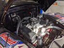
Finally putting crap together, we're just winging it doing everything ourselves. Certainly not without it's flaws, mistakes, lessons. Overall should be a fun truck. Not going to be any hiding that big block when it's running.
1000005412.jpg
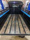
Bed strips and wood all bolted down.
1000005445.jpg
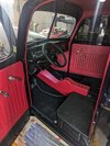
Throwing in all that red, I'm sure it's going to really upset some folks.
1000005446.jpg
 
Top